Index
- BMSBattery S series
- BMSBattery S06S
- S06ST (torque sensor version)
- S06S-BL (Bluetooth version)
- PWM signals
- Phase B current signal
- Throttle
- BMSBattery S06SC
- BMSBattery S12S
- BMSBattery bottle battery controller
- LCD control panel
- Kunteng mobile app
- Bluetooh
- How to open the controller and solder the programming header
- Hardware mods
- Other controllers
- BMSBattery S06P
- Kunteng 18 mosfets motor controller
- Lishui motor controllers
- JinHui motor controllers
- GreenEBikeKit
- Torque speed
- Motor control scheme of S06S controller
- BLDC 6 steps
- PWM schemes
- So, Which PWM Technique is Best? (Part 1)
- So, Which PWM Technique is Best? (Part 2)
- So, Which PWM Technique is Best? (Part 3)
- So, Which PWM Technique is Best? (Part 4)
- So, Which PWM Technique is Best? (Part 5)
- So, Which PWM Technique is Best? (Part 6)
- So, Which PWM Technique is Best? (Part 7)
- PWM control and Dead Time Insertion
- Low inductance motors
- Throttle Control Modes
- Phase angle FOC
- PWM frequency VS motor eRPM
- Sinusoidal Control of BLDCM with Hall Sensors Based
- Self-Learn Hall Sensor Calibration Mode
- STM8S105 Alternatives
- PID algorithm - negative output values
- Regeneration
- FOC
Datasheets and application notes
- STM8S105C6T6
- Endless-sphere.com forum messages
- 2017.04.25 - Initial forum message
- 2017.05.08 - First flash and debug on a dev board
- 2017.05.18 - First code flashing and running
- 2017.05.20 - more new information
- 2017.08.23 - SxxP versus SxxS versus LSW-675
- 2017.09.01 - Trying to figure out an algorithm to automatically adjust ui8_position_correction_value
- 2017.09.02 - How to do FOC on the BMSBattery S06S/Kunteng STM8 motor controllers
- 2017.09.03 - more ideas about zero crossing for FOC
- 2017.09.05 - measuring IQ current and manually adjusting position_correction_value
- 2017.09.15 - our OpenSource firmware efficiency compared to Lishui 12 FET FOC
- 2017.09.19 - measuring motor current
- 2017.10.23 - FOC and no FOC comparison
- 2018.01.10 - How to measure FOC_READ_ID_CURRENT_ANGLE_ADJUST
- 2018.02.20 - Reading motor phase current from the DC link current (shunt)
2017.09.02 - How to do FOC on the BMSBattery S06S/Kunteng STM8 motor controllers
On FOC hardware, typically at least 2 phase currents are measured while on the BMSBattery S06S/Kunteng STM8 motor controllers only 1 phase current is measured. Also FOC needs processing power and we see cheap hardware using like the STM32F103 32 bits that can do the math algorithm while the STM8 8 bits can't.
I think BMSBattery S06S/Kunteng STM8 motor controllers do a kind of simplification of FOC. They can do FOC with much less resolution but that may be enough for this application where the target price of this motor controllers is ultra low. Next, I describe the way I think they achieve FOC.
The following documentation considers that you are familiar with FOC documentation.
The next image shows the 3 phase currents, phased out 120º of each other. On Kunteng STM8 motor controller, only 1 phase current is measured - let's say it is phase A (green line).
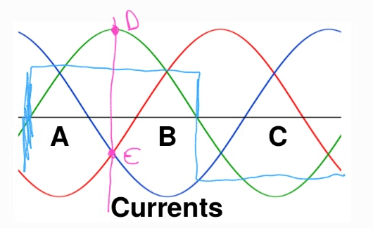
Image 01
ia = green line
ib = red line
ic = dark blue line
hall sensor signal = light blue line
On FOC hardware, typically at least 2 phase currents are measured and since the sum of the 3 phase currents are zero (ia + ib + ic = 0), the third current is calculated.
The next image shows the same current as vectors while teta is zero. Every current is placed 120º phased out of each other.
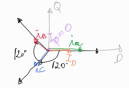
Image 2
The sum of the current values can be represented on the quadrature axis Q and Q (gray color). At the specific moment when teta is zero, ia, ib, ic D axis components results in ID component which should be the max possible value for ID amps (100%). ia, ib, ic Q axis components: ia Q is zero as ia is placed on D axis; ib Q and iC Q have the same value but opposite directions and so they cancel out -- IQ is zero amps (0%).
The next image shows the phase A current with teta 90º relative to motor rotor position - at FOC we want it to be at 90º where happens max efficiency of the motor.
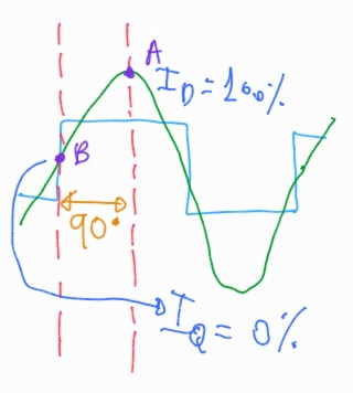
Image 3
hall sensor signal = light blue line
As we can see, ID have the max value, the top of sinewave phase A current value. IQ is measured 90º compared to ID and the phase A current is 0. On FOC we want to keep/control IQ = 0 and that will mean a constant 90º of the phase current relative to motor rotor position, where happens max efficiency of the motor. ID is the value current value that we will also want to control and results of the motor torque.
The next image shows the phase A current with teta 45º relative to motor rotor position. As we can see, IQ is not zero and ID is not the max value -- motor will vibrate, make noise and asking to much current: will be very inefficient.
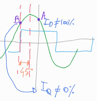
Image 4
The next image shows the phase A current with teta 0º relative to motor rotor position (I think motor would not even work/run on this situation). As we can see, IQ is max value and ID is zero value. With ID zero, we have zero torque meaning motor would not run, I think all the current/torque would be used to block the motor instead of making it rotating.
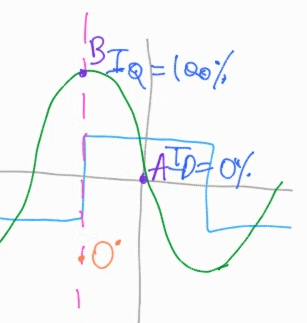
Image 5
Conclusion
I think we can do FOC on the BMSBattery S06S/Kunteng STM8 motor controllers by doing the following:
• please refer to image 3. On this situation, if we read phase current B on Kunteng STM8 motor controller:
◇ point B: the read value is the IQ current
◇ point A: the read value is the ID current
• to do FOC, we need:
◇ keep IQ current = 0
▪ adjust the PWM sinewave phase angle that we generate, to keep IQ at zero amps value
◇ keep ID current at the value we desire, that will result the effective motor current/torque
▪ adjust PWM duty_cycle value to keep ID at the amps value we desire