Index
- BMSBattery S series
- BMSBattery S06S
- S06ST (torque sensor version)
- S06S-BL (Bluetooth version)
- PWM signals
- Phase B current signal
- Throttle
- BMSBattery S06SC
- BMSBattery S12S
- BMSBattery bottle battery controller
- LCD control panel
- Kunteng mobile app
- Bluetooh
- How to open the controller and solder the programming header
- Hardware mods
- Other controllers
- BMSBattery S06P
- Kunteng 18 mosfets motor controller
- Lishui motor controllers
- JinHui motor controllers
- GreenEBikeKit
- Torque speed
- Motor control scheme of S06S controller
- BLDC 6 steps
- PWM schemes
- So, Which PWM Technique is Best? (Part 1)
- So, Which PWM Technique is Best? (Part 2)
- So, Which PWM Technique is Best? (Part 3)
- So, Which PWM Technique is Best? (Part 4)
- So, Which PWM Technique is Best? (Part 5)
- So, Which PWM Technique is Best? (Part 6)
- So, Which PWM Technique is Best? (Part 7)
- PWM control and Dead Time Insertion
- Low inductance motors
- Throttle Control Modes
- Phase angle FOC
- PWM frequency VS motor eRPM
- Sinusoidal Control of BLDCM with Hall Sensors Based
- Self-Learn Hall Sensor Calibration Mode
- STM8S105 Alternatives
- PID algorithm - negative output values
- Regeneration
- FOC
Datasheets and application notes
- STM8S105C6T6
- Endless-sphere.com forum messages
- 2017.04.25 - Initial forum message
- 2017.05.08 - First flash and debug on a dev board
- 2017.05.18 - First code flashing and running
- 2017.05.20 - more new information
- 2017.08.23 - SxxP versus SxxS versus LSW-675
- 2017.09.01 - Trying to figure out an algorithm to automatically adjust ui8_position_correction_value
- 2017.09.02 - How to do FOC on the BMSBattery S06S/Kunteng STM8 motor controllers
- 2017.09.03 - more ideas about zero crossing for FOC
- 2017.09.05 - measuring IQ current and manually adjusting position_correction_value
- 2017.09.15 - our OpenSource firmware efficiency compared to Lishui 12 FET FOC
- 2017.09.19 - measuring motor current
- 2017.10.23 - FOC and no FOC comparison
- 2018.01.10 - How to measure FOC_READ_ID_CURRENT_ANGLE_ADJUST
- 2018.02.20 - Reading motor phase current from the DC link current (shunt)
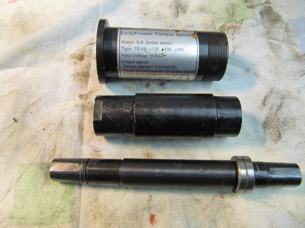
BMSBattery torque sensor
BMSBattery sells a torque sensor for about 50€ (if you don't find on their shop, send them a message ask for it).
You can see it on this video: B.B. Torque Sensor Fatigue Testing
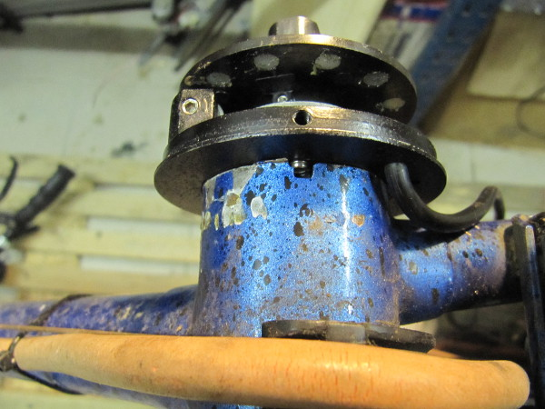
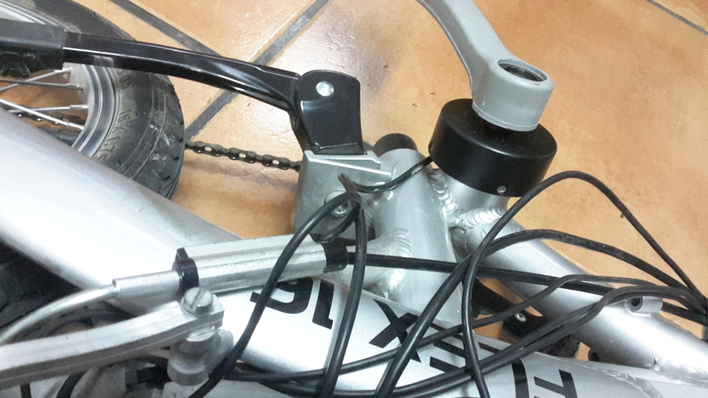
Example of an installed BMSBattery torque sensor:
Connector pins:
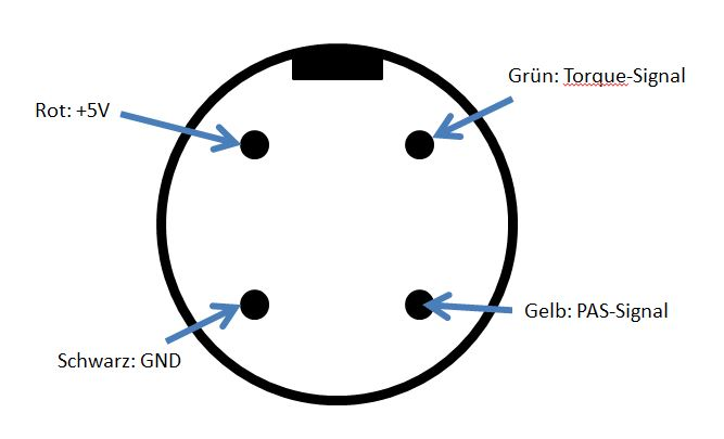
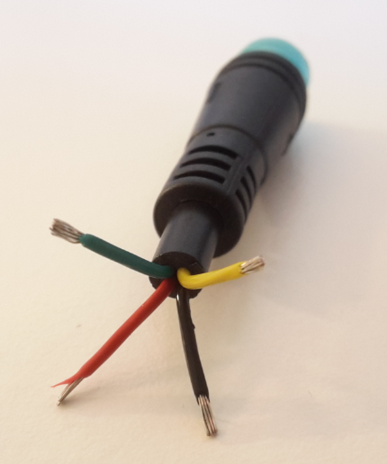
Black: GND
RED: +5V
Yellow: PAS signal
Green: torque signal
Some notes:
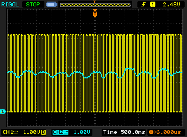
• PAS signal
◇ min of 0 volts and max of 5 volts
◇ seems to always have a duty_cycle of 50%
◇ 12 magnets on the disc → 24 signals changes for each 1 pedals rotation
◇ the signal just changes when rotating forward and not backwards
• torque signal
◇ min of 0.84 volts and max of 4.56 volts
Yellow: PAS signal
Blue: torque signal
Example of a constant cadence and “constant” force applied to the cranks by the foot - note that the torque signal have max and min values:
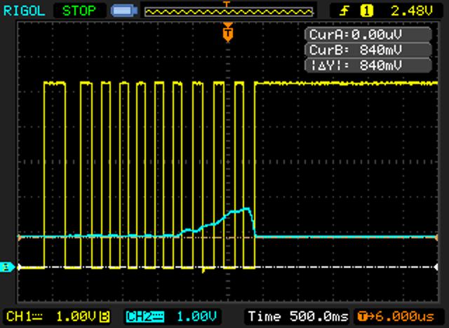
Example of no torque value and increase a bit up to full stop pedaling:
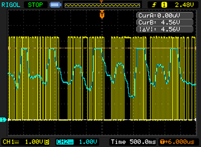
Pedaling strong with quick stops, to see the max output voltage of torque signal:
Information take from this forum message:
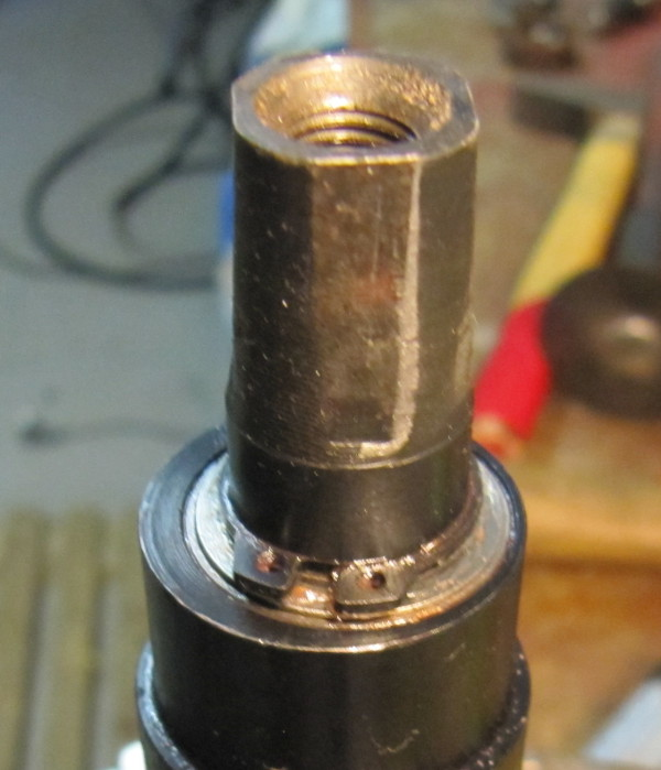
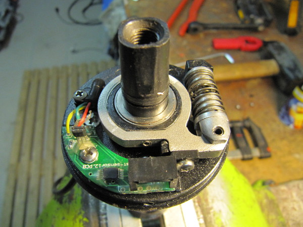
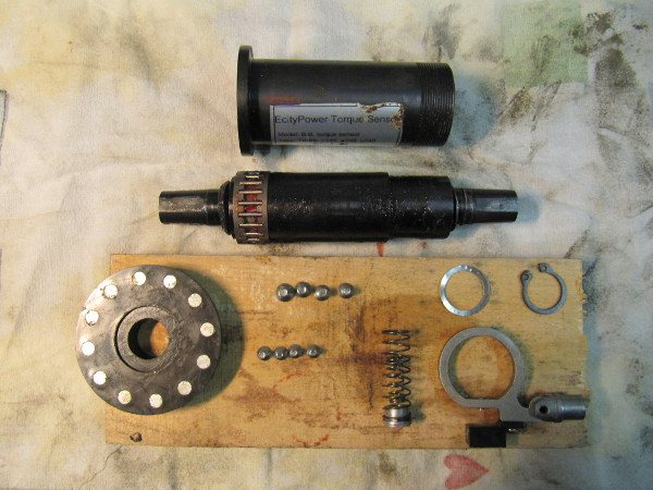
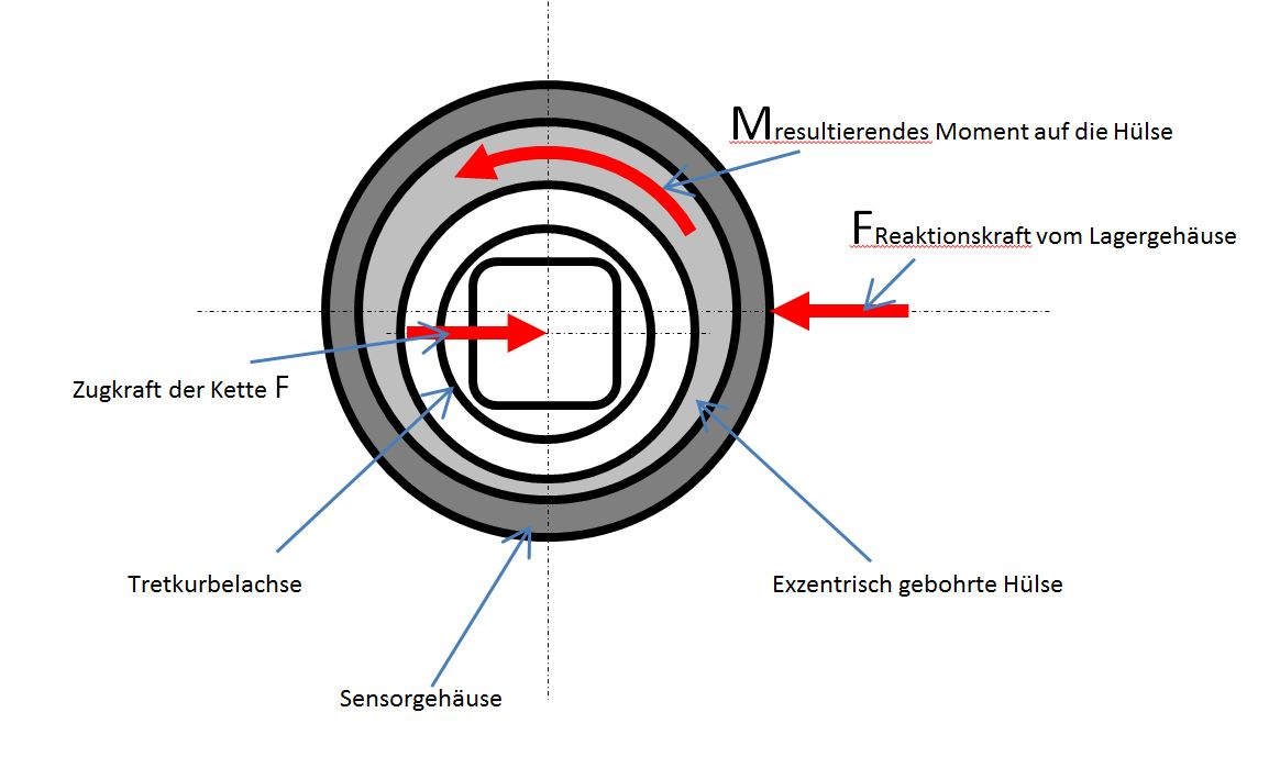
The functional principle is actually simple, but I needed something until I got it. The centerpiece is an eccentrically drilled sleeve. In the sleeve runs the normal massive ball-bearing bottom bracket axle. The sleeve itself is supported by needle bearings in the sensor housing. The whole thing is turned in such a way that the axis lies in the lowest point of the eccentricity. If you now at the bottom dead center on the crank, nothing happens. Even if you blocked the right crank in the horizontal and then on the left on it, nothing happens. Only when the force is really transmitted over the chain, ie acts in the horizontal, created by the eccentricity a moment on the sleeve and this rotates.
The lever is attached to the sleeve with the magnets, which then uses the Hall sensor to convert the mechanical movement into an electrical signal.
In this principle axle and chainring is rigidly connected, so that there is no "rubber feeling" when pedaling.
Since the chain hoist is dependent on the chainring diameter (lever law), the sensor reacts more sensitively to the small chainring (full scale with approx. 15kg weight on the horizontally standing crank) than the big one (full deflection at approx. 25kg).
To install the sensor in the correct position, one of the four screws for fixing the interior is longer. You have to make a slot in the pedal crank of the bicycle frame to mount the bearing.
The whole camp is not screwed into the thread in the frame, but is just clamped. I think that's a bit windy, but that's probably the case with the bottom bracket BBS01.