Index
- BMSBattery S series
- BMSBattery S06S
- S06ST (torque sensor version)
- S06S-BL (Bluetooth version)
- PWM signals
- Phase B current signal
- Throttle
- BMSBattery S06SC
- BMSBattery S12S
- BMSBattery bottle battery controller
- LCD control panel
- Kunteng mobile app
- Bluetooh
- How to open the controller and solder the programming header
- Hardware mods
- Other controllers
- BMSBattery S06P
- Kunteng 18 mosfets motor controller
- Lishui motor controllers
- JinHui motor controllers
- GreenEBikeKit
- Torque speed
- Motor control scheme of S06S controller
- BLDC 6 steps
- PWM schemes
- So, Which PWM Technique is Best? (Part 1)
- So, Which PWM Technique is Best? (Part 2)
- So, Which PWM Technique is Best? (Part 3)
- So, Which PWM Technique is Best? (Part 4)
- So, Which PWM Technique is Best? (Part 5)
- So, Which PWM Technique is Best? (Part 6)
- So, Which PWM Technique is Best? (Part 7)
- PWM control and Dead Time Insertion
- Low inductance motors
- Throttle Control Modes
- Phase angle FOC
- PWM frequency VS motor eRPM
- Sinusoidal Control of BLDCM with Hall Sensors Based
- Self-Learn Hall Sensor Calibration Mode
- STM8S105 Alternatives
- PID algorithm - negative output values
- Regeneration
- FOC
Datasheets and application notes
- STM8S105C6T6
- Endless-sphere.com forum messages
- 2017.04.25 - Initial forum message
- 2017.05.08 - First flash and debug on a dev board
- 2017.05.18 - First code flashing and running
- 2017.05.20 - more new information
- 2017.08.23 - SxxP versus SxxS versus LSW-675
- 2017.09.01 - Trying to figure out an algorithm to automatically adjust ui8_position_correction_value
- 2017.09.02 - How to do FOC on the BMSBattery S06S/Kunteng STM8 motor controllers
- 2017.09.03 - more ideas about zero crossing for FOC
- 2017.09.05 - measuring IQ current and manually adjusting position_correction_value
- 2017.09.15 - our OpenSource firmware efficiency compared to Lishui 12 FET FOC
- 2017.09.19 - measuring motor current
- 2017.10.23 - FOC and no FOC comparison
- 2018.01.10 - How to measure FOC_READ_ID_CURRENT_ANGLE_ADJUST
- 2018.02.20 - Reading motor phase current from the DC link current (shunt)
Regeneration
https://www.roboteq.com/index.php/applications/100-how-to/160-understanding-regeneration
Understanding Regeneration
 Motors become generators when forced to turn while no or reduced power is applied. This phenomenon brings interesting benefits in terms of energy efficiency but it also introduces challenges in system design. Understanding the physics and implications of regeneration is critical in many applications.
Download the original default Application Note (902 KB) .
| Linked file: AN70614-Understanding Regeneration.pdf |
Introduction
Electrical motors are reversible machines; they can function as motors or as generators. A motor receives electrical power from a battery and transforms it in torque developing a Counter Electromotive Force CEMF, which opposes the battery. A generator receives mechanical power from a mechanical actuator and transforms it in electrical power developing a Counter Torque, which opposes the actuator.
A motor behaves as motor and as generator at the same time. In fact while a motor is 'motoring', that is doing mechanical work, it generates CEMF acting as generator, although the CEMF is lower than the battery voltage so the motor acts as a load and absorbs current.
In certain situations the CEMF may overcome the battery, in which case the generator component becomes dominant; the motor acts as a generator inverting the direction of its current and forcing it into the battery.
The typical situation is the one of a heavy vehicle rolling on a sharp downhill slope and forcing the motor to turn fast enough that the CEMF becomes larger than the battery voltage. As soon as the motor overcomes the battery it inverts the current direction and starts feeding current into the battery, while developing a counter torque that acts as a brake. This phase is called regeneration (recharging of the battery).
The Voltage / Current plane
Two wire DC electrical devices have one of the two poles marked as positive. By convention this is the pole where the positive voltage applied or generated is located.
These devices are divided into two categories:
• Generators: Batteries, dynamos, fuel cells etc.
• Users: Resistors, ovens, motors etc.
The current is defined as positive if it enters the positive pole of a user, or exits the positive pole of a generator. See figure 1.
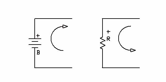
Figure 1.
Obviously it is possible to force a negative current on the positive pole.
As an example, a common car battery (generator) sources a positive current (exiting the positive pole) when starting the car and sinks a negative current (entering the positive pole) while being recharged.
Similarly current can be made to exit from the positive pole of a resistor (user) inverting the voltage across it. By representing positive and negative voltage / current in a plane as VI axis, we distinguish four quadrants.
As an example let's look at a car battery (figure 2); Q1 and Q 3 are the quadrants where the battery acts as a generator, since the current exits the positive pole. In Q1 the generator maintains a positive power rail while in Q3 the battery maintains a negative power rail.
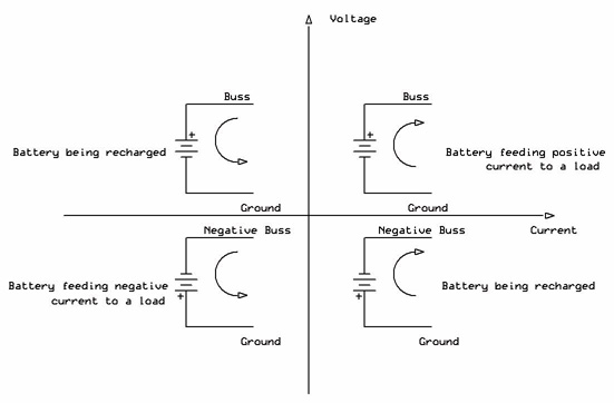
Figure 2.
Q2 and Q4 are the user quadrants, where the battery acts as a load to a battery charger that pushes current into the battery recharging it. In Q2 the battery charger output maintains a positive power rail, where in Q4 the charger maintains a negative power rail.
We will see shortly that a permanent magnet DC motor is also a four-quadrant device, acting as a user in Q1 and Q3, and as a generator in Q2 and Q4.
The motor as a four quadrant device
Most electrical motors operated by a battery use permanent magnet PM motors, since in this case no battery current needs to be spent to generate the magnetic field. Reversing the armature current reverses the direction of rotation.
The only exception is for very large vehicles, where high power motors are needed, beyond the capability of permanent magnets, In this case a 'separately excited' motor is used, mostly the shunt version which, as long as the field winding is feed at constant voltage, behaves like a PM motor (constant flux).
In practice, since the shunt motor may malfunction should the field current accidentally become zero, what is used is a variation of the shunt motor called 'compound'. A small series field winding is added, to guarantee a minimum amount of field as long as there is armature current. An advantage of the shunt motor is that direction is reversed by reversing the field current, rather than the much larger armature current.
The interesting characteristics of the permanent magnet motor are:
• Predictable behavior.
• Ability to develop maximum torque at startup, when speed is zero \
• Absence of run away condition, this being the situation where the motor indefinitely increases its speed, until it destroys itself (something that can happen with separately excited motors).
Ideal in battery operation, since they do nt need to consume current to create the field flux.
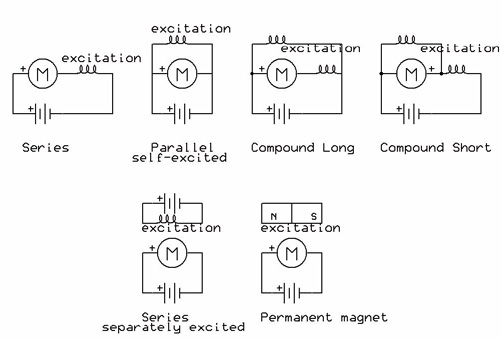
Figure 3.
From now on we refer exclusively to PM motors; they are widely used in many applications up to several HP.
As previously shown, a motor is a reversible machine; it acts in four quadrants of the Voltage / Current plane.
The motor can be assigned a positive pole, which will correspond to one of the two senses of rotation.
Let's assume this is the clock-wise CW direction. Inverting the armature current inverts the direction, which becomes counter-clock-wise CW.
Q1 and Q3 are the quadrants where the motor is motoring, that is absorbing electrical energy and making mechanical work. Q2 and Q4 are the quadrants where the motor is generating, that are it is mechanically pulled, like for example by an electrical golf cart going downhill, and it acts as a DC generator.
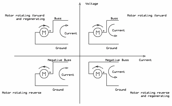
Figure 4.
It is useful to understand the equivalent circuit of a permanent motor. It is composed of a voltage generator equivalent to the Counter Electromotive Force CEMF, a series resistor equivalent to the resistance of the copper of the armature winding, a series inductance.
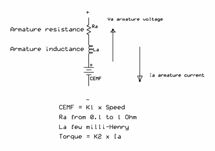
Figure 5.
The figure above shows the electrical equivalent circuit. The flux of the motor is constant so it is incorporated in the constant.
Note that torque is proportional to armature current and CEMF is proportional to the speed; the faster the motor turns, the higher is the CEMF. If the motor is turned by an external agent (gravity on a steep downhill) the CEMF can exceed the voltage of the battery and recharge it.
Energy balance in a vehicle
A moving vehicle has three energy components associated with its motion:
• Kinetic energy EK
• Potential energy EP
• Rotation energy ER
EK = M V2 where M is the mass and V is the speed
EP = M g H where g = 9.8 m/sec2 is the gravity acceleration and H is the height
ER = I W2 where I is the moment of inertia and W the angular velocity
ER is normally very small and can be ignored (unless the vehicle is build on purpose with a heavy spinning wheel, such as boats using gyroscopic rotating masses for stabilization).
The total energy of the vehicle is:
Etot = EK + EP = M ( V2 + 10 H)
We have approximated gravity to 10 meter/second2.
A vehicle engaging an uphill slope will slow down losing kinetic energy (speed diminishes) while gaining potential energy (height increases). A vehicle engaging a downhill slope will lose potential energy (height decreases) and gain kinetic energy (speed increases).
A vehicle going over a summit with its motor disengaged will start moving downhill at constant acceleration until it will reach constant speed. This will happen when attrition and air resistance become sufficiently high to balance gravity. This is similar to a man parachuting who will initially fall at constant acceleration, until wind resistance will balance his speed and keep it constant.
A vehicle going over a summit with its motor engaged will behave in the same way, except that the motor will turn into a generator, effectively adding a braking effect to attrition and wind resistance so the vehicle will reach constant speed sooner and the speed will be lower.
Once the speed becomes constant, the kinetic energy remains constant; only the height decreases by a constant quantity over time. The delta Energy DEP is equal to:
DEP = 10 M (H2 - H1)
H2 is the initial and H1 is the final height.
Let's assume in the last case for simplicity that attrition and wind resistance are negligible, then all the lost potential energy goes into the motor.
If we make the loss of altitude H2 - H2 equal to the loss in one second, then assuming the motor is connected to the battery, then the motor will transform in electrical power the lost Potential Energy per second.
Electrical Power = DEP = 10 M (H2 - H1)
Let's make an example.
A 300 kilograms electrical cart rolls downhill at a constant speed of 15 km/hour (about 10 mile/hour) on a 15% incline. Each second the cart covers four meters.
The loss of height per second is:
H2 - H1 = 4 x 0.15 = 0.6 meters.
The loss of potential energy per second is:
DEp = 10 x 300 x 0.6 = 1,800 Joule per second
In electrical terms this equates to 1.8 kilo Watt of electrical power.
The motor will generate an equivalent current (minus the generator efficiency), which will recharge the battery.
Coasting, Dynamic, Regenerative Braking
Let's assume we have an electric cart reaching a summit and then rolling downhill. As the cart passes the summit, the current in the motor drops to zero as no more torque is requested of the motor. The cart starts rolling downhill at constant acceleration, speeding up and forcing the motor to turn faster and faster so the CEMF increases until the motor turns fast enough that the CEMF exceeds the battery. At that moment the motor becomes a generator and the current will invert its direction and flow into the battery recharging it.
The motor, as generator, will develop a Counter Torque, (equivalent to the motor developing a CEMF) which will act as a brake. Eventually Counter Torque and gravity will balance each other, at which point the cart will stop accelerating and will roll downhill at constant speed.
There are three ways a cart can be designed to handle a downhill:
• Coasting.
The motor is disconnected and left floating. There is no braking effect from the motor and the cart will accelerate so to accumulate the maximum kinetic energy to help with the next uphill climb.
• Dynamic braking
The motor is detached from the battery and connected to a resistor. The potential energy lost downhill is dissipated as heat. The motor acts as a brake but the energy is lost as heat.
• Regenerative braking
The motor stays connected to the battery and the CEMF (once exceeding the battery) will recharge the battery. The motor acts as a brake and the lost potential energy is stored in the battery.
Using a Power Supply
In some stationary application a power supply may be used instead of a battery; in this case regenerative braking may become dangerous.
A battery is a four-quadrant device, capable of issuing (discharge) or receiving (recharge) current maintaining its voltage costant.
A power supply in general is designed as a one-quadrant generator, designed for issuing current at constant voltage, but not for receiving it.
If a power supply has to be used, then the best choice is a conventional power supply with large filtering output electrolytic capacitors; a regenerating motor will charge the capacitors and as long as the voltage does not exceed their maximum rating, the power supply will operate in two quadrants. A switching power supply in general is not suitable. Consult the Roboteq literature on this subject.
The variable speed electronic motor controller
A Roboteq Variable Speed Electronic Motor Controller is a device capable of regulating direction and speed of a motor. This is achieved by using a Power MOS bridge. The controller controls the direction of a motor by conducting on one side or the other side, which effectively inverts the current in the motor.
Speed is controlled by pulsating the Top MOS on one side of the bridge, while the Bottom MOS on the other side is always ON (PWM regulation); the speed will be proportional to the Duty Cycle of the PWM.
The Bottom MOS on the same side of the bridge of the Pulsating MOS is pulsated too in opposition to the Top MOS (the two must never be ON at the same time, or they will short the power supply with consequent damage to the controller).
The reason for pulsating the Bottom MOS is to provide a low resistance path to the inductive current of the motor, which is made safely re-circulate avoiding the typical high voltage spikes generated by an inductive load.
The Figure below illustrates the concept. At the top the Power Bridge is shown when the battery feeds the motor, and at the bottom when the motor re-circulates.
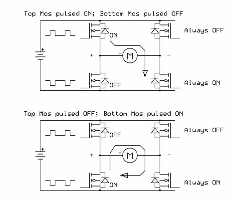
Figure 6.
In the figure above both the controller and the motor have been conventionally assigned a positive pole, which for the controller corresponds to a positive current being generated and for the motor corresponds to the forward sense of rotation. Clearly this is a convention, as neither the controller nor the motors are in reality sold with a positive pole clearly marked.
Reversing the power bridge would reverse the sense of rotation of the motor, which would rotate backwards.
Less intuitive is the operation in the second and fourth quadrant, where the motor would generate current. To better understand this let's refer to the practical situation of a vehicle in motion.
A consequence of the motor current re-circulation is that the motor current is almost constant (effectively filtered by the inductance of the motor). Typically the inductance of a motor is few milli-Henry while the internal resistance is at least 100 milli-Ohm, so the time constant T = L/R is in at least 10 millisecond, much lager than the PWM frequency, hence the smoothing of the current into an almost DC current.
The figure below shows how the Power Bridge chops the battery current, while allowing the motor current to be DC. In essence the controller maintains the battery voltage constant and chops the battery current, while in turn chopping the motor voltage and maintaining constant the motor current.
Obviously the power generated by the battery must be equal to the power given to the motor (the controller has very high efficiency). Indicating the duty cycle as DC:
Power generated by the battery:
Vbb x Iaverage = Vbb x Ipeak x DC
Power received by the motor:
Imot x Vmot = Imot x Vbb x DC
Therefore:
Vbb x Ipeak x DC = Imot x Vbb x DC
Ipeak = Imot / DC
As an example, measuring 5 Amp continuous current in the motor when the duty cycle is 10% means that the peak of current in the battery is 50 Amp, something to take into account in designing the mechanical and electrical power connections.
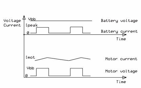
Figure 7.
In reality what described above is not what is observed, since the current at the battery Ibb is close to a DC current, due to the smoothing effect of the of large electrolytic capacitors mounted in the controller.
Consequently the battery delivers a constant amount of power (constant voltage/constant current):
Pbb = Vbb x Ibb
The motor conversely has its voltage Vbb chopped by the duty cycle DC and a constant current Imot; the two powers need to be the same, therefore:
Vbb x Ibb = (Vbb x DC) x Imot Imot = Ibb / DC
In conclusion the current flowing in the motor is larger than the current measured at the battery except than when the duty cycle becomes 100%.
The example above refers to the controller and the motor in the first quadrant,
The motor as a generator
Figure 8 depicts an electrical vehicle climbing an incline moving forward (top) or in reverse (bottom). When the vehicle rolls downhill it will turn the motor pressed by the force of gravity so the motor will actually turn into a generator.
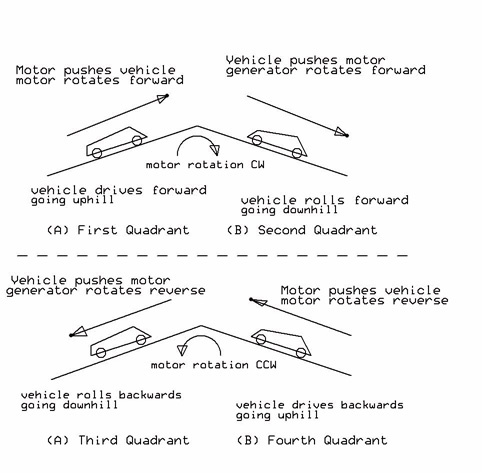
Figure 8.
When the vehicle is climbing the motor will absorb current; once the vehicle reaches the summit the torque required will drop significantly and the motor current will drop practically to zero. When the vehicle rolls down the downhill slope the current will actually invert direction and flow into the controller.
It has to be noted that the voltage generated by the motor as a generator is proportional to the speed; as soon as the vehicle slows down the motor stops regenerating.
It should be noted that the vehicle has three key parameters; let's see how they affect the electronics:
• Direction: the vehicle can move Forward or Backwards.
The motor will correspondently rotate CW or CCW (as a convention)
• Gear: the gear can be D (Drive), N (Neutral), R (Reverse).
The gear affects which leg of the power bridge switches.
A gear in N is equivalent to a throttle fully released (DC = 0)
• Throttle: can be pressed or released (same as gear in Neutral).
The throttle controls the DC.
Direction and Gear do not necessarily correspond. The operator of a vehicle rolling downhill may from time to time engage the gear in Reverse to slow down the descente so Gear and Direction will be in opposition from time to time.
Obviosly if a vehicle moves Forward and the operator engages the gear in Reverse, sooner or later the vehicle will invert direction and go Backwards. In other words gear and direction can be opposing only for a limited period of time.
Also if DC = 0, then both top MOS Q! and Q3 are OFF, while both bottom MOS are ON. The motor is effectively shorted (Dynamic Braking).
Concurrent and Opposing Regeneration
Let's look more in detail in how regenration works.
For simplicity we assume DC = 100%.
As long as the vehicle climbs uphill the power bridge will work as depicted in fig 9-A.
Once it starts rolling downhill, it will pickup speed and the CEM voltage will increase; as soon as it will exceed the battery voltage, the motor will turn into generator and the motor current will invert and will start flowing from the motor into the battery, fig 9 - B.
Let's assume that the operator wants to slow down and does this throwing the gear in R, still with the throttle fully pressed (not a very safe procedure, but let's assume).
The gear will switch the leg so now Q2 and Q3 will be ON while Q1 and Q4 will be OFF,
fig 9- C.
As long as the vehicle continues forward the motor will still rotate CW.
Eventually the vehicle will come to a stop and start again backwards; the motor will be motoring and pushing the vehicle backwards uphill.
Let's look at the two regenerative situations B and C.
In B the current flows in the opposite direction as when the battery works normally, we call this Opposing Regeneration.
In C the polarity across the motor is inverted and the motor current will enter the negative pole of the battery and exit the positive pole. Since the current flows in the same direction as when the battery works normally, we call this Concurrent Regeneration.
While this is still regeneration, we can see that the current no longer recharges the battery.
It takes Opposing Regeneration to recharge the battery.
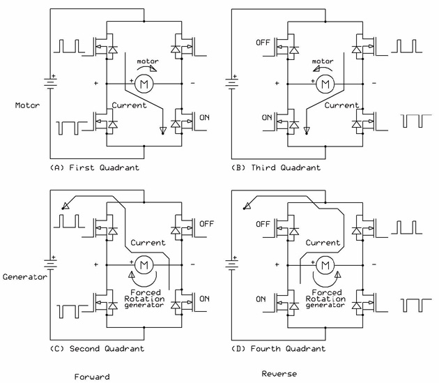
Figure 9.
Regenerative braking
Regeneration subtracts mechanical energy from the vehicle to generate electric energy; as a consequence there is a slow down in the speed of the vehicle (regenerative braking).
The braking effect is quite different among Oppsing, Concurrent Regeneration and Dynamic Braking (please note that Dynamic Braking is just another form of regeneration, where the generator is shorted).
Assuming the generator develops a Voltage Vm, its internal resistance is Rm and it develops the current Im, if Vbb is the battery voltage then we can calculate the power generted in the three cases:
• Opposing Regeneration
P = (Vm - Vbb)2/ Rm
• Dynamic braking
P = Vm / Rm
• Concurrent Regeneration
P = (Vm + Vbb)2 / Rm
Let's look at a practical case of a 24 Volt system where the motor has an internal resistance of 1 Ohm and it develops 30 Volt regenerative voltage.
• Opposing Regeneration
P = (30 - 24)2 x 1 = 36 Watt
Soft braking
• Dynamic braking
P = 302 x 1 = 900 Watt
Medium braking
• Concurrent Regeneration
P = (30 + 24)2 x 1 = 2.5 kWatt
Hard braking
It is obvious that Concurrent rgeneration can be sustained for only for an extremely short period of time while Opposing Regeneration can be sustained for as long as there is a downhill slope.
In practice Opposing Regeneration and Dinamic Braking cohesist; infact most of the time there is a Duty Cycle and in the first part of the DC the generator pushes current into the battery (Regeneration) , while in the second part of the duty cycle the generator is shorted (Dynamic Braking).
The Duty Cycle mixes the two kinds of braking.
By adjusting the throttle the braking mix can be changed from all Opposing (DC = 100%) to all Dynamic
(DC = 0) so releasing the throttle has the effect of making the braking progressively less soft.
Battery disconnect during Regeneration
From the above discussion it is obvious that it is essential that the battery is connected; should the battery become disconnected, then the generator would feed the controller through the body diode of the top MOS.
As a consequence the control logic is active and one of the two bottom MOS will be turned ON for the time of the duty cycle, (example Q2).
The bottom MOS Q2 will attempt to drag to GND the terminal M1+ but in doing so it will suppress the voltage that feeds the control logic, so Q2 will be turned OFF and the terminal M1+ will jump back to Vmot. An equlibrium situation will establish itself, where Q2 will be ON and force M1+ to drop to where there is still enough voltage to keep the control logic fed.
See fig 10
Essentially M1+ will settle around 9 volt, and Q2 will draw the current:
I2 = (Vm - 10) / Rm
Unfortunately Q2 power dissipation will be:
P = 9 x I2
It is easy to see that the power dissipation may easily reach hundreds of watt, with instant damage to Q2.
Let's assume Vm = 24 volt and Rm = 1 Ohm.
We will ahve:
I2 = (24 - 10) / 1 = 14 Amp
P = 9 x 14 = 126 Watt
Unfortunately this may happen an an often overlooked situation, that is the pushing into parking position of a vehicle that has been de-activated.
If the main switch has been opened disconnecting the battery, then pushing the vehicle has the effect of turning the motor and even at low speed the motor will generate some voltage Vm.
It is enough that Vm reaches 8 to 10 Volt to put in Q2 in jeopardy.
On the other side if the terminal Vcon (the thin yellow wire in the AX2550) is grounded, then all MOS are OFF and no damage can occur as long as the regenration voltage Vm does not exceed the maximum voltage rating.
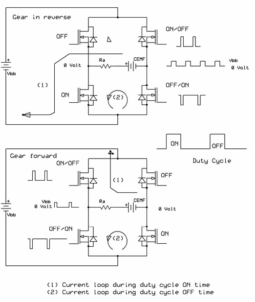
Figure 10.
Preventing Damage from Regeneration with a Disconnected Battery
Care should be exercised when inserting switches, relays, contactors between the battery and the controller, which can disconnect the battery from the controller.
Similarly diodes in series with the battery have a similar effect since they would prevent the regeneration current from circulating back into the battery..
The best defense against regeneration over-voltage is to have the battery always connected. Where this is impossible, then the following would protect the controller.
Use the terminal Vcon to turn ON and OFF the controller.
Fig 11 - A
If a main switch is required, use a DPDT switch, where the second pole grounds the terminal Vcon.
fig 11 - B
If a fuse and a main switch are required, put a diode in parallel to the fuse and the main switch.
fig 11 - C
If an emergency switch is required, without anything in parallel to it for safety reasons, then a combination DPDT and diode will provide sufficient protection.
fig 11-D
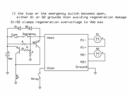
Figure 11.
Appendix A - Sizing the motor
There are many power train calculators on the Web, so rather than repeating one here, we take the opportunity to show on which formulas are they based.
Let's assume we want to determine the size of the motor needed to accelerate a 300-kilo mass M golf cart from zero to 15 kilometer/hour speed S up a 20% incline I reaching final speed in 10 seconds.
The speed V in meter / second is:
V = 15,000 / 3,600 = 4.2 meter / second
The constant acceleration A required will be:
A = V / Time = 4.2 / 10 = 0.42 meter / sec2
The space S covered by the cart is equal to:
S = A T2 S = 0.5 x 0.42 x 10 x 10 = 21 meter
The cart will climb according to the slope I gaining H elevation:
H = I x S = 0.2 x 21 = 4.2 meter
The cart energy will go from zero to Etot, where
Etot = EK + EP = M (V2 + 10 H) = 300 x (0.5 x 4.22 + 10 x 4.2) = 15,246 Joules
The power P will be:
P = Etot / Time = 15,246 / 10 = 1,525 Joule/sec = 1,525 Joule / sec
Since 1 HP is equal to approximately 750 Joule / sec, the HP rating of the motor is:
HP = 1,525/ 750 = 2 HP
Assuming a 24 Volt battery system, considering the average efficiency of a motor is 75%, the electrical power required by the motor will be:
Electrical Power = 1,525 Watt / 0.75 = 2,033 Watt
Motor Current = Electrical Power / Battery Voltage = 2,033 / 24 = 85 Amp