Index
- BMSBattery S series
- BMSBattery S06S
- S06ST (torque sensor version)
- S06S-BL (Bluetooth version)
- PWM signals
- Phase B current signal
- Throttle
- BMSBattery S06SC
- BMSBattery S12S
- BMSBattery bottle battery controller
- LCD control panel
- Kunteng mobile app
- Bluetooh
- How to open the controller and solder the programming header
- Hardware mods
- Other controllers
- BMSBattery S06P
- Kunteng 18 mosfets motor controller
- Lishui motor controllers
- JinHui motor controllers
- GreenEBikeKit
- Torque speed
- Motor control scheme of S06S controller
- BLDC 6 steps
- PWM schemes
- So, Which PWM Technique is Best? (Part 1)
- So, Which PWM Technique is Best? (Part 2)
- So, Which PWM Technique is Best? (Part 3)
- So, Which PWM Technique is Best? (Part 4)
- So, Which PWM Technique is Best? (Part 5)
- So, Which PWM Technique is Best? (Part 6)
- So, Which PWM Technique is Best? (Part 7)
- PWM control and Dead Time Insertion
- Low inductance motors
- Throttle Control Modes
- Phase angle FOC
- PWM frequency VS motor eRPM
- Sinusoidal Control of BLDCM with Hall Sensors Based
- Self-Learn Hall Sensor Calibration Mode
- STM8S105 Alternatives
- PID algorithm - negative output values
- Regeneration
- FOC
Datasheets and application notes
- STM8S105C6T6
- Endless-sphere.com forum messages
- 2017.04.25 - Initial forum message
- 2017.05.08 - First flash and debug on a dev board
- 2017.05.18 - First code flashing and running
- 2017.05.20 - more new information
- 2017.08.23 - SxxP versus SxxS versus LSW-675
- 2017.09.01 - Trying to figure out an algorithm to automatically adjust ui8_position_correction_value
- 2017.09.02 - How to do FOC on the BMSBattery S06S/Kunteng STM8 motor controllers
- 2017.09.03 - more ideas about zero crossing for FOC
- 2017.09.05 - measuring IQ current and manually adjusting position_correction_value
- 2017.09.15 - our OpenSource firmware efficiency compared to Lishui 12 FET FOC
- 2017.09.19 - measuring motor current
- 2017.10.23 - FOC and no FOC comparison
- 2018.01.10 - How to measure FOC_READ_ID_CURRENT_ANGLE_ADJUST
- 2018.02.20 - Reading motor phase current from the DC link current (shunt)
2017.09.19 - measuring motor current
The next tests were done with firmware running the very low resolution FOC and the motors were running with the best efficiency possible up to date.Schematic of the part to measure motor current:
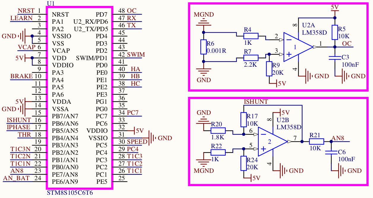
Over current (OC)
LM358D U2A seems to be configured as a comparator, comparing the voltage on the shunt.
On pin 3, the voltage is defined by the voltage divider R9 and R7:
R7/(R7+R9) * Vin = Vout; 2.2 / (2.2 + 20) * 5V = 0.099 * 5V = 0.5v
If R6 = 0.001R; OC signal will be active low when current I = U / R; I = 0.5 / 0.001 = 500 amps (??)
Opamp as diferential amplifier (motor current)
LM358D U2B seems to be configured as a differential comparator and the output is the amplified signal of motor current (ISHUNT). This signal is after sent through the low pass filter formed by the R21 and C6, resulting in the signal AN8.
Diferential amplifer gain:
Gain = (R3/R1) * (V2-V1) = 10/1.8 * (V R6 - 0) --> gain = 5.56
Vout = 1.59V, measured with motor stopped. For each 1A, Vout will increase:
V R6 = 0.001 * 1 = 0.001V; 0.001 * 5.56 (gain) = 5.6mV (??)
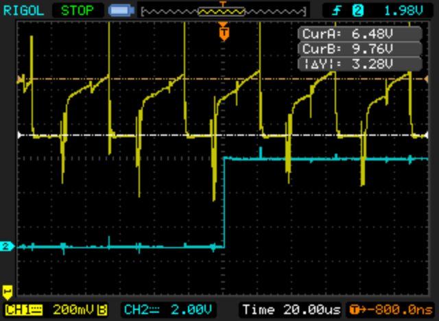
Oscillocope screenshot showing with yellow the ISHUNT signal and blue the AN8 signal. Note that both signal values with the motor stopped were 1.59V.
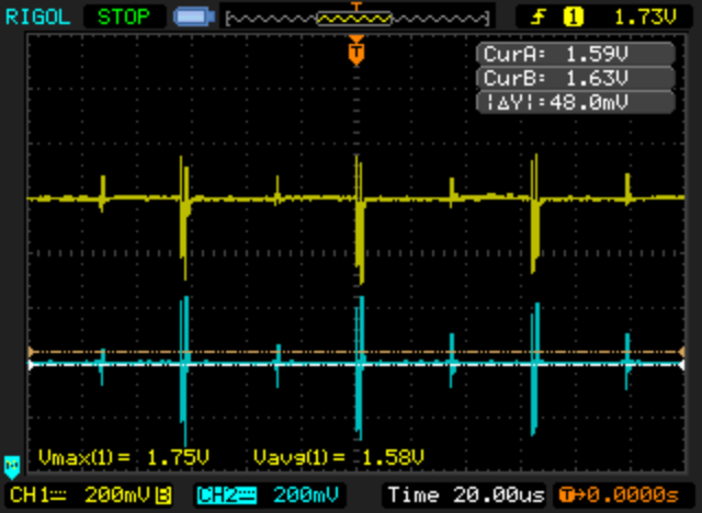
Now with the motor running and the lab power supply were showing a current value of 1.1A.
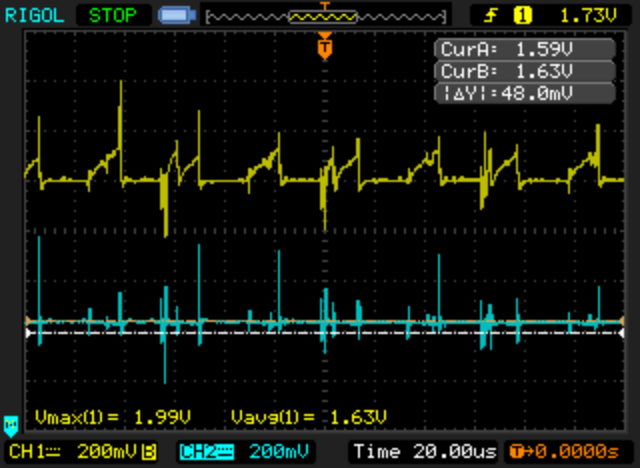
As we can see, for a current of 1.1A, the AN8 signal is about 48mV higher (lab power supply measures 0.2A with motor stopped). Each 1A should increase the signal about 53mV.
EUC2 motor (direct drive motor)
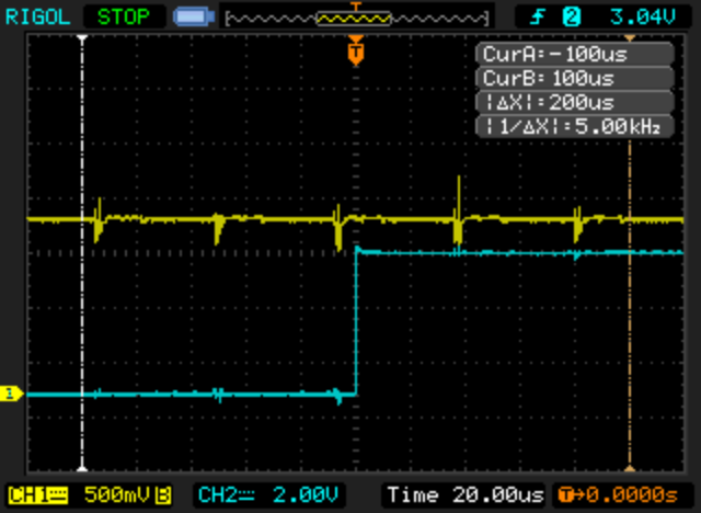
Motor running slow and without load. Yellow is the ISHUNT signal, blue is hall sensor signal. Power supply current measuring 0.2A:
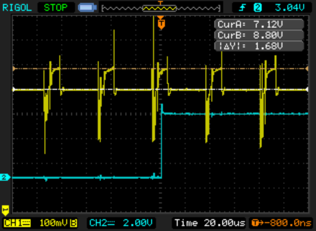
Motor running slow and now with a load. Power supply current measuring 1A. 80mV peak current:
Q85 motor (geared motor)
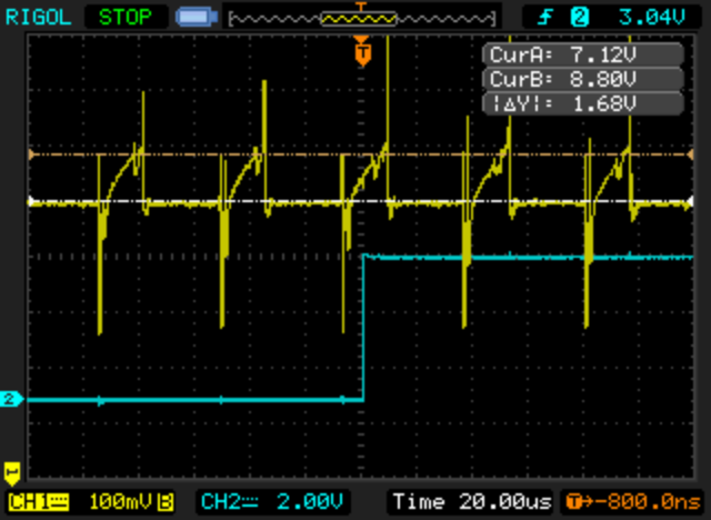
Motor running slow and without load. Power supply current measuring 0.5A. 80mV peak current:
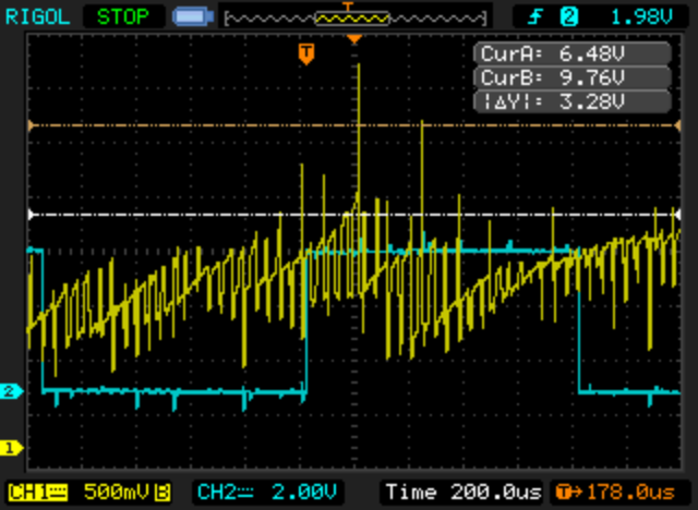
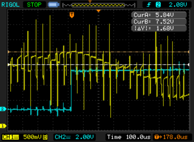
Motor running at medium/high speed and without load. 320mV peak current:
Motor running at high speed and without load but here the motor makes a lot of noise and vibration. The lab power supply were indicating “short-circuit” protection so motor should not run like this.
500mV at least peak current including negative peak currents: