Index
- BMSBattery S series
- BMSBattery S06S
- S06ST (torque sensor version)
- S06S-BL (Bluetooth version)
- PWM signals
- Phase B current signal
- Throttle
- BMSBattery S06SC
- BMSBattery S12S
- BMSBattery bottle battery controller
- LCD control panel
- Kunteng mobile app
- Bluetooh
- How to open the controller and solder the programming header
- Hardware mods
- Other controllers
- BMSBattery S06P
- Kunteng 18 mosfets motor controller
- Lishui motor controllers
- JinHui motor controllers
- GreenEBikeKit
- Torque speed
- Motor control scheme of S06S controller
- BLDC 6 steps
- PWM schemes
- So, Which PWM Technique is Best? (Part 1)
- So, Which PWM Technique is Best? (Part 2)
- So, Which PWM Technique is Best? (Part 3)
- So, Which PWM Technique is Best? (Part 4)
- So, Which PWM Technique is Best? (Part 5)
- So, Which PWM Technique is Best? (Part 6)
- So, Which PWM Technique is Best? (Part 7)
- PWM control and Dead Time Insertion
- Low inductance motors
- Throttle Control Modes
- Phase angle FOC
- PWM frequency VS motor eRPM
- Sinusoidal Control of BLDCM with Hall Sensors Based
- Self-Learn Hall Sensor Calibration Mode
- STM8S105 Alternatives
- PID algorithm - negative output values
- Regeneration
- FOC
Datasheets and application notes
- STM8S105C6T6
- Endless-sphere.com forum messages
- 2017.04.25 - Initial forum message
- 2017.05.08 - First flash and debug on a dev board
- 2017.05.18 - First code flashing and running
- 2017.05.20 - more new information
- 2017.08.23 - SxxP versus SxxS versus LSW-675
- 2017.09.01 - Trying to figure out an algorithm to automatically adjust ui8_position_correction_value
- 2017.09.02 - How to do FOC on the BMSBattery S06S/Kunteng STM8 motor controllers
- 2017.09.03 - more ideas about zero crossing for FOC
- 2017.09.05 - measuring IQ current and manually adjusting position_correction_value
- 2017.09.15 - our OpenSource firmware efficiency compared to Lishui 12 FET FOC
- 2017.09.19 - measuring motor current
- 2017.10.23 - FOC and no FOC comparison
- 2018.01.10 - How to measure FOC_READ_ID_CURRENT_ANGLE_ADJUST
- 2018.02.20 - Reading motor phase current from the DC link current (shunt)
So, Which PWM Technique is Best? (Part 2)
https://e2e.ti.com/blogs_/b/motordrivecontrol/archive/2012/03/26/so-which-pwm-technique-is-best-part-2So, Which PWM Technique is Best? (part 2)
Dave Wilson, Motion Products Evangelist, Texas Instruments
So, which PWM technique is best for your motor control application? In the previous blog, we examined the single-quadrant PWM technique, which is a good fit for extremely cost sensitive motor control applications where you want to control the motor’s speed by varying the duty-cycle of a PWM signal. But the motor can only spin in one direction, and generate torque in that same direction. We also introduced the “H-Bridge” as a springboard to investigate other PWM topologies. In this blog, let’s take a look at how to build a bi-directional speed control power stage by using an H-Bridge. In particular, we will construct a 2-Quadrant Drive since it can produce forward motion with positive torque (quadrant 1), or reverse motion with negative torque (quadrant 3). Again we will choose a DC motor for this discussion, since the concepts are more easily understood with a DC motor.
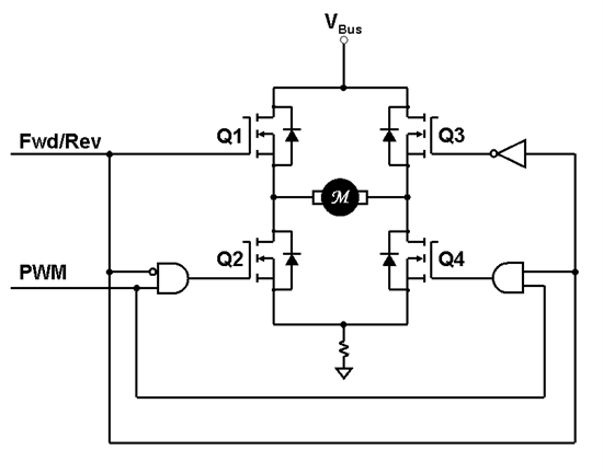
For Unipolar PWM operation in quadrant 1, Q1 is turned ON continuously while we apply a PWM signal to Q4. You can watch an animation of Unipolar PWM operation in quadrant 1 by clicking here. When Q4 is switched ON, a current path is created from Vbus, through Q1, through the motor, through Q4, and returning through ground. At the end of this PWM state, Q4 is switched OFF. Since the motor winding has inductance, it will fight to keep the motor current flowing in the same direction. An inductor protects its current just like a mother protects her child. It effectively says, “Don’t mess with my current! If you do, I will generate whatever voltage is necessary to keep my current flowing.” As a result, the inductor forces the back-body diode of Q3 to conduct. But since Q1 is always ON, the motor current will return through Q1, not the DC supply. When you think about it, you realize that since Q1 is ON continuously, this circuit behaves exactly like the single quadrant drive discussed earlier with one exception…if you want the motor to spin in the other direction, simply turn Q3 ON all the time and PWM Q2 instead. This results in quadrant 3 operation where the motor is running in reverse, and generating negative torque. You can see an animation of this process by clicking here.
It’s interesting to note that in both quadrant one and quadrant three operation, the bus current is either positive or zero, regardless of which direction the current is flowing in the motor! In other words, this PWM technique cannot regenerate energy. The reason for this is because the inductive flyback current is “trapped” in the top half of the H-Bridge, and never flows back into the DC bus. This can either be an advantage or a disadvantage, depending on your application. If you never have to worry about regenerated energy, then you don’t have to add expense to your design to deal with it. On the other hand, if you want to recover load energy, then this PWM technique is not a good choice for you.