Index
- BMSBattery S series
- BMSBattery S06S
- S06ST (torque sensor version)
- S06S-BL (Bluetooth version)
- PWM signals
- Phase B current signal
- Throttle
- BMSBattery S06SC
- BMSBattery S12S
- BMSBattery bottle battery controller
- LCD control panel
- Kunteng mobile app
- Bluetooh
- How to open the controller and solder the programming header
- Hardware mods
- Other controllers
- BMSBattery S06P
- Kunteng 18 mosfets motor controller
- Lishui motor controllers
- JinHui motor controllers
- GreenEBikeKit
- Torque speed
- Motor control scheme of S06S controller
- BLDC 6 steps
- PWM schemes
- So, Which PWM Technique is Best? (Part 1)
- So, Which PWM Technique is Best? (Part 2)
- So, Which PWM Technique is Best? (Part 3)
- So, Which PWM Technique is Best? (Part 4)
- So, Which PWM Technique is Best? (Part 5)
- So, Which PWM Technique is Best? (Part 6)
- So, Which PWM Technique is Best? (Part 7)
- PWM control and Dead Time Insertion
- Low inductance motors
- Throttle Control Modes
- Phase angle FOC
- PWM frequency VS motor eRPM
- Sinusoidal Control of BLDCM with Hall Sensors Based
- Self-Learn Hall Sensor Calibration Mode
- STM8S105 Alternatives
- PID algorithm - negative output values
- Regeneration
- FOC
Datasheets and application notes
- STM8S105C6T6
- Endless-sphere.com forum messages
- 2017.04.25 - Initial forum message
- 2017.05.08 - First flash and debug on a dev board
- 2017.05.18 - First code flashing and running
- 2017.05.20 - more new information
- 2017.08.23 - SxxP versus SxxS versus LSW-675
- 2017.09.01 - Trying to figure out an algorithm to automatically adjust ui8_position_correction_value
- 2017.09.02 - How to do FOC on the BMSBattery S06S/Kunteng STM8 motor controllers
- 2017.09.03 - more ideas about zero crossing for FOC
- 2017.09.05 - measuring IQ current and manually adjusting position_correction_value
- 2017.09.15 - our OpenSource firmware efficiency compared to Lishui 12 FET FOC
- 2017.09.19 - measuring motor current
- 2017.10.23 - FOC and no FOC comparison
- 2018.01.10 - How to measure FOC_READ_ID_CURRENT_ANGLE_ADJUST
- 2018.02.20 - Reading motor phase current from the DC link current (shunt)
So, Which PWM Technique is Best? (Part 3)
https://www.ecnmag.com/article/2012/04/so-which-pwm-technique-best-part-3So, which PWM technique is best? (Part 3)
Thu, 04/05/2012 - 6:17am by Dave Wilson, Motion Products Evangelist, Texas Instruments
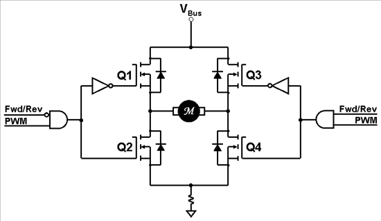
So, which PWM technique is best for your motor control application? So far we have studied two motor drive topologies that result in unipolar PWM voltage waveforms on the motor, but are incapable of providing any braking for the motor in the event you want to decelerate quickly. In this blog, let’s look at a third unipolar PWM technique that will provide motor braking by allowing energy regeneration back into your power supply. We call this “Unipolar 4-Quadrant PWMs” (Form 1). The H-Bridge circuit that we will analyze is shown below:
The most significant change from the previous unipolar topology is that we are now driving the top and bottom transistors in a complementary pattern. In other words, whenever a bottom transistor is turned OFF, the top transistor in the same leg is turned ON, and vice versa. Not shown in the diagram is an implied dead-time from when one transistor turns OFF until its complementary transistor turns ON. With most power FETs, this dead-time can be in the area of about 100 nanoseconds to almost 1 uS. The quickest dead-time I have ever seen is on our DRV-8312 device, which is 5 nS! Since dead-time causes distortion which is associated with the current zero-crossings, a small dead-time of 5 nS results in almost NO distortion at all.
 So, Which PWM Technique is Best? (part 3)
Returning to our circuit example above, let’s analyze the condition where Fwd/Rev is set to 1 (forward motion). This means that Q1 will be ON continuously while Q3 and Q4 are PWMing in a complementary fashion. Let’s also assume that the PWM duty-cycle is high and the motor loading is light, which means that the motor speed will also be high and the back-EMF polarity is such that it is positive on the left side of the motor symbol.
Now let’s abruptly lower the PWM duty cycle in an effort to decelerate the motor. With 2-quadrant PWMs, whenever Q4 turns off, the inductive flyback current is captured in the top half of the H-Bridge until it is extinguished. Once the flyback current is extinguished, the back-EMF signal appears across the motor terminals. In this state, the H-Bridge looks like a high impedance to the motor, and no current flows. But with this 4-quadrant topology, when Q4 is OFF, Q3 turns ON, and we effectively short the motor terminals together. Since the motor is spinning forward (back-EMF polarity is positive on the left side of the motor), this eventually causes current to flow in the clockwise direction in the top half of the H-Bridge.
Now, this next point is important. When Q3 is now switched OFF, and Q4 is switched ON, the inductor now looks for an alternate path to keep its current flowing in the same direction. And what is that path? It turns out that the new path of least resistance is to flow in the reverse direction through Q1, back through the DC power supply AS NEGATIVE CURRENT, and then return in the reverse direction through Q4. If your DC bus has positive voltage and negative current, then that means that it has negative power during that instance. This negative bus current will charge up the bus capacitor to a higher voltage until the inductive flyback is quenched, or the next switching state is applied.
You should be aware that the presence of negative bus current in and of itself does not imply that we are regenerating. Momentary values of negative bus current are common, as energy can slosh back and forth between the motor inductor and the bus capacitor within each PWM cycle. To determine if regeneration is occurring, we must look at the average value of bus current. If the average value is negative, then we have a long-term transference of energy from the load back to your DC supply. If you follow the energy, you have kinetic energy (1/2 mass x speed2) being converted to magnetic energy (1/2 L i2), and finally being stored in the bus capacitor as 1/2 C v2.
Words are good; pictures are great, but sometimes, you just have to see it for yourself to understand what is going on. The best way to do this is on a lab bench where you roll up your shirtsleeves, grab an oscilloscope probe and have some fun! However, the next best way to understand this concept is to watch a simulation. To that end, I have created a VisSim simulation showing two identical motors with identical loads, supplied with identical PWM values. However, one motor is driven with unipolar 2-quadrant PWMs, and the other is driven with unipolar 4-quadrant PWMs. You can access the simulation here. If you don’t have VisSim already installed on your computer, it’s not a problem. You can download a 60-day trial version from Visual Solutions’ website here, or download a file viewer program here. With the trial version, you have access to all the features, and you can even change the simulation topology to test other ideas if you wish. With the viewer, you can adjust everything that I provide an adjustment for, but you can’t change the structure of the simulation itself, nor can you save any changes.
So go ahead and open the simulation and have some fun! Adjust the PWM duty cycle to a large value, and let the motors ramp up to speed. Then quickly bring the duty cycle down toward zero. Motor 1 (which utilizes a 2-quadrant PWM) will coast down slowly. But Motor 2 (which utilizes the 4-quadrant PWM we have just introduced) will decelerate quickly. This is because regen is occurring on Motor 2, as indicated by the red regen light on its H-Bridge. A screenshot of the simulation is shown below.
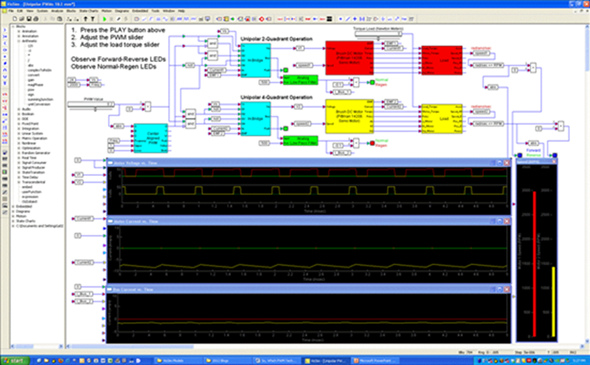 A screenshot of the simulation
Now try this: With the PWM still set to a positive value, change the load torque to be negative. Almost immediately, Motor 2 starts to regen, as indicated by the red light on its power stage. However, Motor 1 cannot regenerate, and you can watch the motor accelerate out of control since there is no braking. Finally, when the motor back-EMF reaches the power supply voltage, you will see the regen light for Motor 1 come on too. This is because the back-EMF voltage for Motor 1 exceeds the power supply voltage, causing negative current to spill into the bus.
Returning to the top diagram above, as long as current is flowing in the shunt resistor, we have visibility to the motor current. However, all the PWM techniques we have discussed so far have blackout periods when the motor current is recirculating within the H-Bridge and not flowing through the shunt resistor. Also, when the pulse width is very narrow, the sampling window closes up so as to make it impossible to acquire a current sample. This limits us to one current sample per PWM period, and also places limits on the PWM duty cycle. However, in our next blog, we will explore the BIPOLAR PWM technique which permits us to sample the current at twice the PWM frequency in most cases, and always has at least one window per PWM period that is wide enough to acquire the current sample, regardless of the PWM duty cycle value. Until then...
Keep those motors spinning! :-)