Index
- BMSBattery S series
- BMSBattery S06S
- S06ST (torque sensor version)
- S06S-BL (Bluetooth version)
- PWM signals
- Phase B current signal
- Throttle
- BMSBattery S06SC
- BMSBattery S12S
- BMSBattery bottle battery controller
- LCD control panel
- Kunteng mobile app
- Bluetooh
- How to open the controller and solder the programming header
- Hardware mods
- Other controllers
- BMSBattery S06P
- Kunteng 18 mosfets motor controller
- Lishui motor controllers
- JinHui motor controllers
- GreenEBikeKit
- Torque speed
- Motor control scheme of S06S controller
- BLDC 6 steps
- PWM schemes
- So, Which PWM Technique is Best? (Part 1)
- So, Which PWM Technique is Best? (Part 2)
- So, Which PWM Technique is Best? (Part 3)
- So, Which PWM Technique is Best? (Part 4)
- So, Which PWM Technique is Best? (Part 5)
- So, Which PWM Technique is Best? (Part 6)
- So, Which PWM Technique is Best? (Part 7)
- PWM control and Dead Time Insertion
- Low inductance motors
- Throttle Control Modes
- Phase angle FOC
- PWM frequency VS motor eRPM
- Sinusoidal Control of BLDCM with Hall Sensors Based
- Self-Learn Hall Sensor Calibration Mode
- STM8S105 Alternatives
- PID algorithm - negative output values
- Regeneration
- FOC
Datasheets and application notes
- STM8S105C6T6
- Endless-sphere.com forum messages
- 2017.04.25 - Initial forum message
- 2017.05.08 - First flash and debug on a dev board
- 2017.05.18 - First code flashing and running
- 2017.05.20 - more new information
- 2017.08.23 - SxxP versus SxxS versus LSW-675
- 2017.09.01 - Trying to figure out an algorithm to automatically adjust ui8_position_correction_value
- 2017.09.02 - How to do FOC on the BMSBattery S06S/Kunteng STM8 motor controllers
- 2017.09.03 - more ideas about zero crossing for FOC
- 2017.09.05 - measuring IQ current and manually adjusting position_correction_value
- 2017.09.15 - our OpenSource firmware efficiency compared to Lishui 12 FET FOC
- 2017.09.19 - measuring motor current
- 2017.10.23 - FOC and no FOC comparison
- 2018.01.10 - How to measure FOC_READ_ID_CURRENT_ANGLE_ADJUST
- 2018.02.20 - Reading motor phase current from the DC link current (shunt)
Sensorless Pneu Scooter - part 2
Sunday, December 18, 2011
Sensorless Pneu Scooter: Part 2
Pneu Scooter is now Sensorless Pneu Scooter! (Which means I can ride it again.)
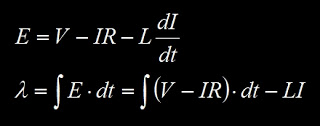
This is the follow-up to Part 1: Where I make my code much fancier. Most of the work of the past two weeks went into setting up a new timing structure for the control code, which is summarized by this graphic. The controller has a fast loop, which runs at 15.625kHz, and a slow loop, which runs at just under 1kHz. The slow loop handles the computationally-burdensome Field-Oriented Control (FOC) calculations, and hasn't changed since I first implemented it on B.W.D. long ago. The concept of FOC is summarized in these two posts, and is shown in this, the first of many neon graphics I color-inverted for this post:
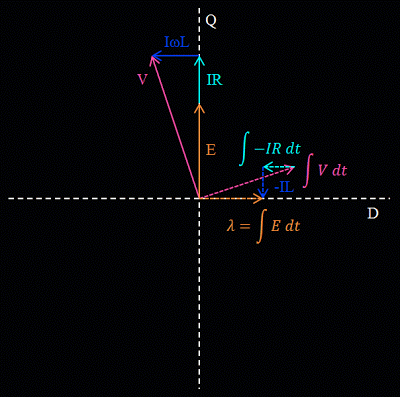
FOC seeks to keep stator current, I, in phase with back EMF, E, which is equivalent to saying that it keeps stator flux 90º ahead of rotor flux. This produces the most torque per amp. To keep the current and back EMF in phase, the voltage, V, is phase-advanced by the controller to counteract the effect of inductance.
All these quantities are treated as vectors (really, the magnitude and relative phase of a set of balanced three-phase sine waves). The coordinate system is aligned with the rotor's magnetic field (hence, "field-oriented") and the axis on which the rotor flux is at a maximum is called the Direct (D) Axis. The Quadrature (Q) Axis leads the D-Axis by 90º electrical in the direction of rotation.
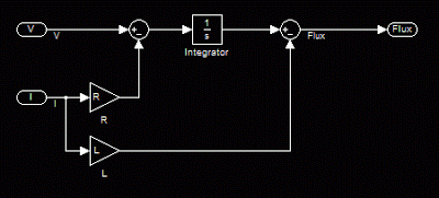
Because the coordinate system is locked to and spinning with the rotor, the position of the rotor must be known with good resolution for any of this to work. Previously, I used Hall effect sensors and time-based interpolation to derive the position. But, as the name would imply, Sensorless Pneu Scooter needs new tricks that do not rely on Hall effect sensors. To obtain the rotor position, the fast loop estimates flux on all three phases. The flux estimator I chose to start with is a very simple one:
It's an "open-loop" flux observer that derives the rotor flux linkage from measured currents, driven voltages, and a good estimate of the motor's resistance, R, and inductance, L. The vector version of this flux estimator is shown in the image above. Note that the integral of a given vector is another vector which lags by 90º and is scaled by the angular frequency:
Which brings up another good point: Unlike back EMF, flux does not vary with speed, so the flux estimator should produce a constant magnitude at any speed. As the V and E vectors increase in magnitude, the scaling by ω keeps the integral-form from growing.
The figure above is actually somewhat misleading. For one, the flux estimator doesn't run in the rotating D/Q coordinate system, but rather in the stationary frame, on each of the three phases independently. Also, the estimated flux on each phase is a scalar quantity; it's just the magnitude of the rotor flux seen by that particular motor phase at that particular instant. To derive position from this, I take an unusual approach of watching for flux zero-crossings (with hysteresis) and feeding these transitions to the same interpolation routine that my Hall effect sensors would have gone to.
In this way, the flux estimator is always running in parallel with the Hall effect sensors and control can be given to either one at any point in time. Additionally, they can be compared to each other. So, as I've been test-driving with the sensorless position estimate in control, I've been logging data from both. Cue the rest of the neon graph sequence:
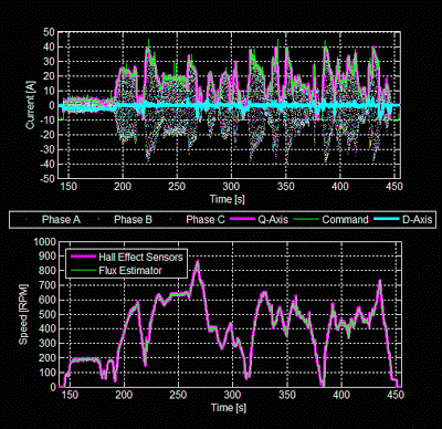
All of the the data in this post was recorded during a five-minute outdoor test drive with the sensorless position estimate running the field-oriented control. The top plot above shows effective regulation of Q-Axis current to follow the throttle command, and the D-Axis current being held close to zero. The bottom plot shows the speed estimates produced by both the Hall effect sensors and the flux estimator. (Both calculate speed by measuring the time for one full period of rotor flux.) They are nearly identical at all speeds, including below 100rpm.
Speed is not sufficient for control, though; the flux estimator needs to be able to accurately derive the rotor position. Comparing the rotor position derived by the flux estimator to that of the Hall effect sensors reveals the following:
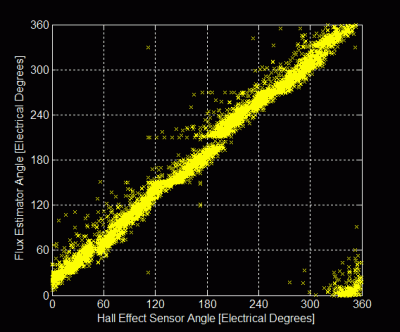
The ideal case would be a straight line with a slope of one, indicating perfect agreement between the flux estimator and the Hall effect sensors. There is a good deal of noise in the position estimate, but the general 1:1 correlation is there. The flux estimator angle leads the Hall effect sensor angle slightly, shifting the entire line upwards by about 15º. This is not necessarily the fault of the flux estimator; it could be interpreted as the Hall effect sensors being about 15º behind neutral timing.
To get more of a feel for the source of the noise around the 1:1 line, I plotted the relative phase offset between the flux estimator's angle and the Hall effect sensor angle as a function of a few other quantities. First, speed:
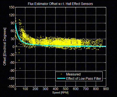
There are several interesting bits of information in this plot:1. At any speed, the band of uncertainty in the position estimate is still about 30º. Therefore, there must be factors other than speed which cause offset in the position estimate.
2. The bulk shift of 15º (flux estimator leading Hall effect sensors) is clear in this plot too.
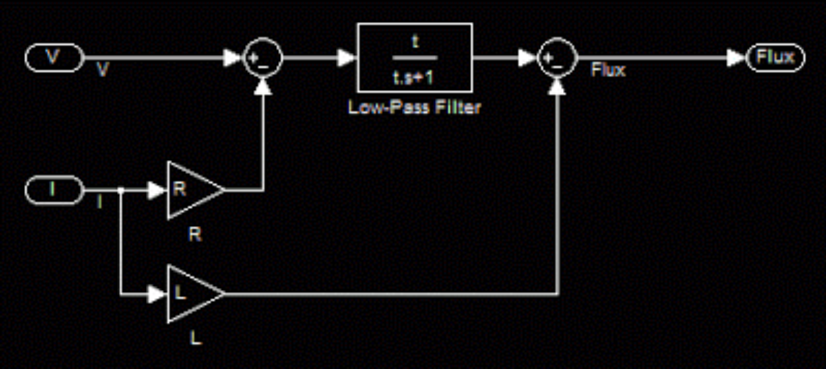
3. At low speeds, the flux estimator leads the Hall effect sensors even more. This one is easy to explain. Instead of a pure integrator, I implemented a low-pass filter on (V-IR) as part of the flux esimator:
| click me |
|---|
| Pure integrator. |
| click me |
|---|
| Low-pass filter. |
The low-pass filter is used to keep the integral from drifting away. It's combined with a gain of τ, the filter time constant, so that at high frequencies it looks like a pure integrator. But at low frequencies, it has less than the -90º of phase a pure integrator would give:
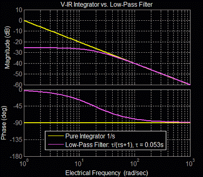
At the corner frequency I chose for the low-pass filter, 0.053s, the low-pass filter causes the flux estimator to lead significantly at low speeds. The blue line in the offset vs. speed plot above is the theoretical lead induced by the low-pass filter. Setting the filter time constant to be longer would push the speed at which lead becomes significant down lower. Since the data seems to clearly show this effect, I would like to run some tests where all I change is the low-pass filter time constant. Obviously a longer time constant would be better for low speed operation. Integral drift might hurt the performance overall, though.
I also plotted the offset between the flux estimator angle and the Hall effect sensor angle as a function of load (Q-Axis current):
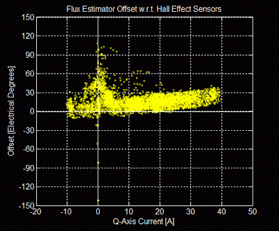
Here, another clear trend was revealed: the flux estimator lead increases with current. My hypothesis on this one is that the inductance estimate is low. In the first graphic of this post, the -IL vector would be too short if L were underestimated. This would cause the estimated flux to be somewhere in the upper-right quadrant, leading the true flux, which is on the D-Axis. Again, since the data shows a very clear trend, I would like to run some test where I vary only the inductance parameter to see if I can flatten out this line.
This particular dependency (position error as a function of load) is one that I think can be avoided as I pursue more advanced sensorless algorithms. A "closed-loop" flux observer would be able to more readily handle misidentified motor parameters by using feedback to adapt the motor model or negate some of the effects of the misidentified parameter. Another valid option is to have the motor parameters self-calibrate, either at power-on or dynamically as it runs.
Lastly, my favorite graph of all:
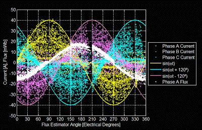
I had the data spit back the actual flux estimate on Phase A along with all the phase currents. Plotting the Phase A flux as a function of the flux estimator's angle reveals a very nice sinusoidal flux that peaks at 180º and has an amplitude of about 15-17mWb. Not coincidentally, this is close to 1/7th of the motor's per-phase back EMF constant of 0.105V/(rad/s) = 0.105Wb. (The motor has seven pole pairs.)
The three phase currents are also plotted and are bounded by nice 40A sine waves, representing maximum positive throttle. Phase A's current (yellow) leads Phase A's flux (white) by about 90º, as it should if the field-oriented control is doing its job.There's a very interesting gap in the flux estimate angle just before 210º, which is also seen as a "staircase" effect in the flux estimator angle vs. Hall effect sensor angle plot. I still haven't tracked this one down or formed a theory about it yet, but this convinces me that it's an issue inherent to the flux estimate, since this plot has nothing to do with the Hall effect sensors.
Altogether, this "simple" sensorless routine has been working very well since I modified the controller timing. I can't say I understand exactly why (or even if) the changes I made to the loop timing caused it to start working, but I'm happy that it's now producing useful data and that I have new tests to try out.
I'm even more happy that my Pneu Scooter riding ban can be lifted since it's now capable of propelling itself in 100% sensorless mode.
Posted by Shane Colton at 1:07 AM Labels: field-oriented control, FOC, pneu, pneu scooter, sensorless