Index
- BMSBattery S series
- BMSBattery S06S
- S06ST (torque sensor version)
- S06S-BL (Bluetooth version)
- PWM signals
- Phase B current signal
- Throttle
- BMSBattery S06SC
- BMSBattery S12S
- BMSBattery bottle battery controller
- LCD control panel
- Kunteng mobile app
- Bluetooh
- How to open the controller and solder the programming header
- Hardware mods
- Other controllers
- BMSBattery S06P
- Kunteng 18 mosfets motor controller
- Lishui motor controllers
- JinHui motor controllers
- GreenEBikeKit
- Torque speed
- Motor control scheme of S06S controller
- BLDC 6 steps
- PWM schemes
- So, Which PWM Technique is Best? (Part 1)
- So, Which PWM Technique is Best? (Part 2)
- So, Which PWM Technique is Best? (Part 3)
- So, Which PWM Technique is Best? (Part 4)
- So, Which PWM Technique is Best? (Part 5)
- So, Which PWM Technique is Best? (Part 6)
- So, Which PWM Technique is Best? (Part 7)
- PWM control and Dead Time Insertion
- Low inductance motors
- Throttle Control Modes
- Phase angle FOC
- PWM frequency VS motor eRPM
- Sinusoidal Control of BLDCM with Hall Sensors Based
- Self-Learn Hall Sensor Calibration Mode
- STM8S105 Alternatives
- PID algorithm - negative output values
- Regeneration
- FOC
Datasheets and application notes
- STM8S105C6T6
- Endless-sphere.com forum messages
- 2017.04.25 - Initial forum message
- 2017.05.08 - First flash and debug on a dev board
- 2017.05.18 - First code flashing and running
- 2017.05.20 - more new information
- 2017.08.23 - SxxP versus SxxS versus LSW-675
- 2017.09.01 - Trying to figure out an algorithm to automatically adjust ui8_position_correction_value
- 2017.09.02 - How to do FOC on the BMSBattery S06S/Kunteng STM8 motor controllers
- 2017.09.03 - more ideas about zero crossing for FOC
- 2017.09.05 - measuring IQ current and manually adjusting position_correction_value
- 2017.09.15 - our OpenSource firmware efficiency compared to Lishui 12 FET FOC
- 2017.09.19 - measuring motor current
- 2017.10.23 - FOC and no FOC comparison
- 2018.01.10 - How to measure FOC_READ_ID_CURRENT_ANGLE_ADJUST
- 2018.02.20 - Reading motor phase current from the DC link current (shunt)
PWM signals
• PWM frequency
• 6 steps and sinewave
• PWM low and high sides microcontroller signal
• Negative side dead time
• Positive side dead time
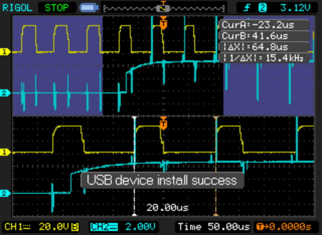
PWM frequency
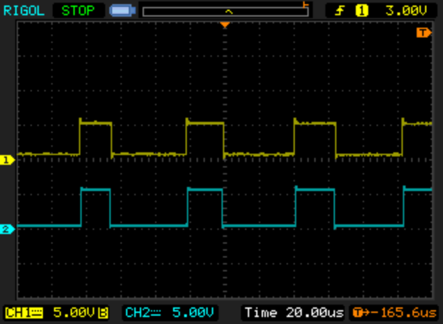
PWM frequency is about 15.4kHz:
6 steps and sinewave
At start very low speed, the PWM LOW driver sides don't have PWM, just are HIGH or LOW. After this phase, the motor starts to run in Sine Wave and both PWM driver sides have PWM.
Sinewave commutation seems to happen at about ~30 erps, even if the motor has or not a load.
After entering in sinewave, will stay in that mode until motor stops, which may happens at very low speeds like 10 or less erps.
Is possible to see that Sine Wave is drive by SVM (Space Vector Modulation).
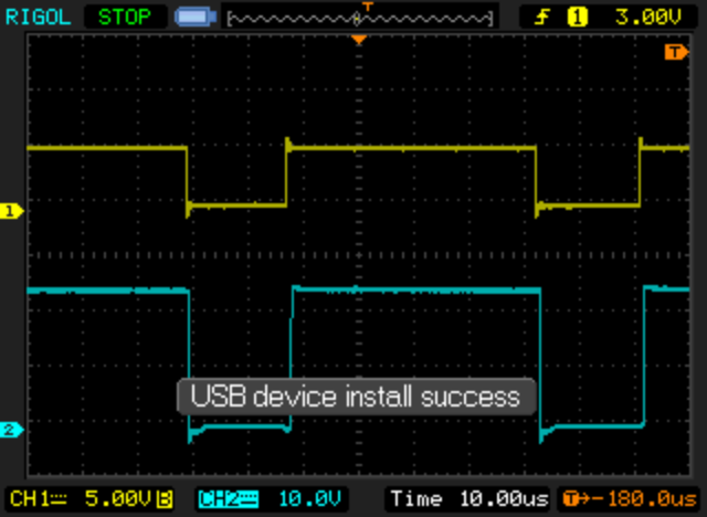
PWM low and high sides microcontroller signal
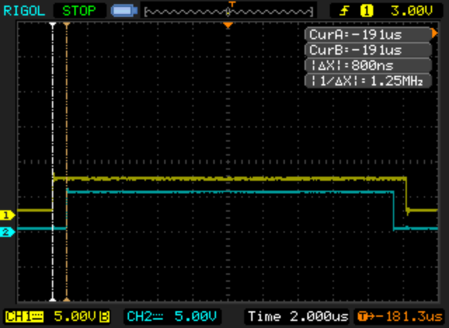
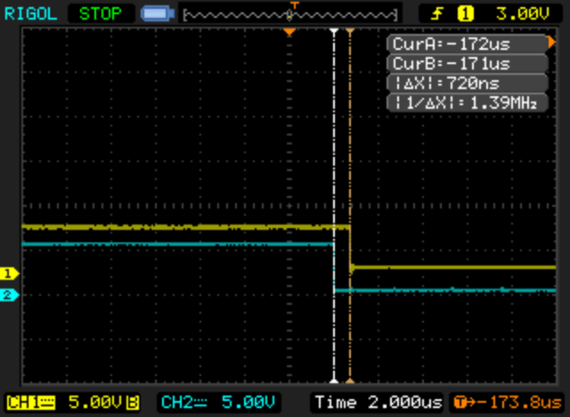
• the low side have a positive polarity and as also the high side
• the low side signal is about 800ns + 800ns larger than high side signal
• yellow: TIM1_CH2N
• blue: TIM1_CH2
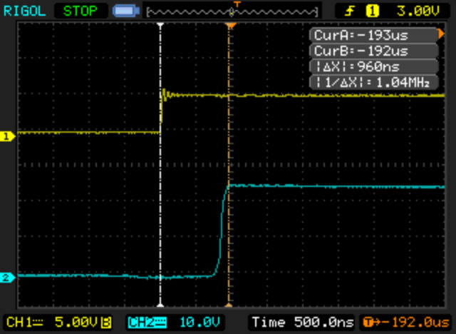
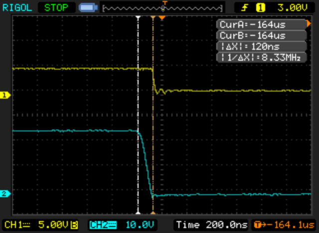
Negative side dead time
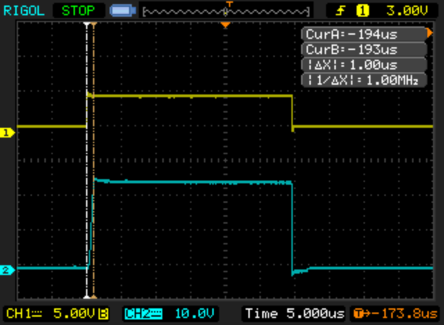
• about 1us rise time
• about 0.12us fall time
• yellow: TIM1_CH2N
• blue: phase voltage
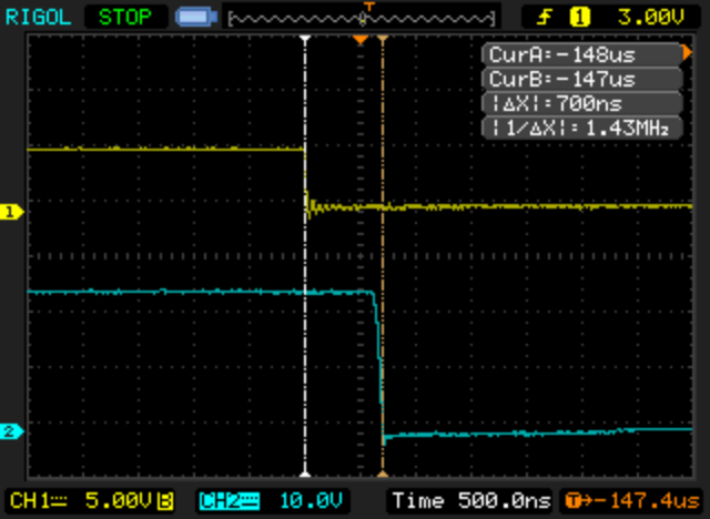
Positive side dead time
• about 1us rise time
• about 0.7us fall time
• yellow: TIM1_CH2
• blue: phase voltage
