Index
- BMSBattery S series
- BMSBattery S06S
- S06ST (torque sensor version)
- S06S-BL (Bluetooth version)
- PWM signals
- Phase B current signal
- Throttle
- BMSBattery S06SC
- BMSBattery S12S
- BMSBattery bottle battery controller
- LCD control panel
- Kunteng mobile app
- Bluetooh
- How to open the controller and solder the programming header
- Hardware mods
- Other controllers
- BMSBattery S06P
- Kunteng 18 mosfets motor controller
- Lishui motor controllers
- JinHui motor controllers
- GreenEBikeKit
- Torque speed
- Motor control scheme of S06S controller
- BLDC 6 steps
- PWM schemes
- So, Which PWM Technique is Best? (Part 1)
- So, Which PWM Technique is Best? (Part 2)
- So, Which PWM Technique is Best? (Part 3)
- So, Which PWM Technique is Best? (Part 4)
- So, Which PWM Technique is Best? (Part 5)
- So, Which PWM Technique is Best? (Part 6)
- So, Which PWM Technique is Best? (Part 7)
- PWM control and Dead Time Insertion
- Low inductance motors
- Throttle Control Modes
- Phase angle FOC
- PWM frequency VS motor eRPM
- Sinusoidal Control of BLDCM with Hall Sensors Based
- Self-Learn Hall Sensor Calibration Mode
- STM8S105 Alternatives
- PID algorithm - negative output values
- Regeneration
- FOC
Datasheets and application notes
- STM8S105C6T6
- Endless-sphere.com forum messages
- 2017.04.25 - Initial forum message
- 2017.05.08 - First flash and debug on a dev board
- 2017.05.18 - First code flashing and running
- 2017.05.20 - more new information
- 2017.08.23 - SxxP versus SxxS versus LSW-675
- 2017.09.01 - Trying to figure out an algorithm to automatically adjust ui8_position_correction_value
- 2017.09.02 - How to do FOC on the BMSBattery S06S/Kunteng STM8 motor controllers
- 2017.09.03 - more ideas about zero crossing for FOC
- 2017.09.05 - measuring IQ current and manually adjusting position_correction_value
- 2017.09.15 - our OpenSource firmware efficiency compared to Lishui 12 FET FOC
- 2017.09.19 - measuring motor current
- 2017.10.23 - FOC and no FOC comparison
- 2018.01.10 - How to measure FOC_READ_ID_CURRENT_ANGLE_ADJUST
- 2018.02.20 - Reading motor phase current from the DC link current (shunt)
Sensorless - 2011.07.05
Tuesday, July 5, 2011
http://scolton.blogspot.pt/2011/07/sensorless-foc-more-analysis.html
Sensorless FOC: More Analysis
I've been away from hardware for a (much needed) week off. But whenever I'm away from hardware, I inevitably start to think about software. So for the last couple of days I've been going back over all the references I've collected for sensorless field-oriented control, partly to refresh my memory, partly to categorize and compare them, and partly to choose one to actually implement.
I feel like this is where I should make fun of myself for being a grad student and spending all my time thinking about the solution instead of actually solving the problem. But I think in this one particular case, the analysis time will pay back many times over if I correctly choose an approach that will actually work as opposed to one that only works on paper, with properly-chosen gains, and ideal current sensors, and a perfect system model, and on a Wednesday with low relative humidity.
First, a baseline against which to compare any potential solution: In the post where I first looked into sensorless field-oriented control, I put up the following bit of motor math:
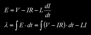
This shows how you can estimate the back EMF or the flux linkage using only the voltage applied to the terminals of the motor and the measured current. You can do this on any phase of the motor to find the back EMF of that phase. The flux linkage will give a somewhat cleaner estimate in real life because it doesn't need the derivative of a noisy current signal. You can also convert all the quantities into vectors and find the magnitude and phase of the resultant flux linkage. The phase of the flux linkage is the rotor electrical angle, and can be used for field-oriented control.
The drawback of this approach is that it's entirely open-loop, which means it is heavily dependent on model accuracy. If the values for resistance or inductance are off, the estimate will have a magnitude and phase error, and the phase error will hurt the performance of the FOC. It's still a valid approach, though, and almost certain to be stable. So any alternative closed-loop approach must outperform this baseline.
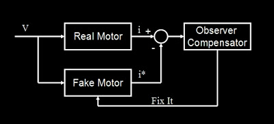 The general idea of a closed-loop observer.
Last post, I had become a fan of Microchip AN1078's
| Linked file: Microchip-AN1078-Sensorless_Field_Oriented_Control_of_PMSM_Motors.pdf |
closed-loop observer, so I'll start with my latest impressions of that one. It's a sliding-mode observer, which in this case means that the thing occupying the Observer Compensator black box is just a comparator. If the estimated current is higher than the measured current, it feeds back +K, else, it feeds back -K. So, it's not a linear observer. The switching structure appealed to me because
1. It's computationally easy, saving precious time in the fast loop that would otherwise be spent multiplying out linear observer feedbacks.
2. It is highly noise-immune with respect to the current sensor signal. As long as the noise is unbiased (zero mean) and of high enough frequency, it will get drowned out by the switching feedback. This is a huge benefit since my controllers so far have had pretty crappy current sensors.
The part that confused me about AN1078 is what the Fake Motor box does with the stream of +K/-K feedback. It applies a series of low-pass filters which magically produce the back EMF estimate, but doesn't show mathematically why this is the case. More disturbingly, it requires a "phase compensation" which is simply pulled from a look-up table. The explanation for this? "It is recommended that phase compensation be fine tuned for any particular motor." It might still be better than the open-loop estimate, but a true observer should not need phase compensation as a function of motor speed.
I decided that I won't be taken seriously as a grad student unless I run MATLAB Simulations for a significant portion of my life:
| click me |
|---|
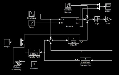
| Microchip AN1078 in Simulink |
That is Microchip's AN1078 observer implemented in Simulink, including the phase compensation (bottom left). It's estimating the back EMF on a single phase, but the same exact observer could be used to estimate the two back EMF vector components (often called α and β components). The values used for the motor model come from Pneu Scooter's wheel motor, since it'll likely be the first test of any sensorless FOC I implement.
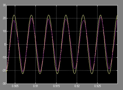
At first glance, AN1078 does pretty well:
| click me |
|---|
| Yellow: Actual back EMF. Purple: Estimated back EMF. |
This is at at about 2,000rpm and 40A peak amplitude, with all model parameters accurately tuned. The phase compensation is taken to be the combined phase of the two low-pass filters at this electrical frequency. (Or, sticking with the Microchip plan, pulled from a look-up table.) The phase of the back EMF estimate is insensitive to current sensor noise, applied voltage phase, and a wide parameter variation of resistance. But, crucially, it doesn't seem to like error in the inductance parameter of the model. With the inductance set to 1.5x the true value...
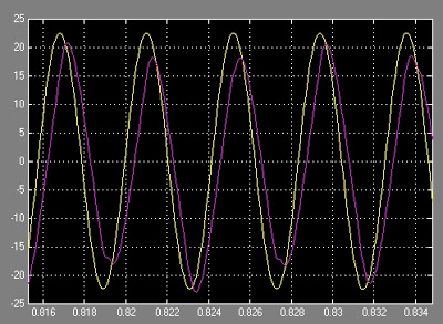
| click me |
|---|
| Yellow: Actual back EMF. Purple: Estimated back EMF. |
...the back EMF estimate lags significantly. The inductance is the harder parameter to measure, so an error of 50% or even more must be tolerable. Increasing the feedback gain can diminish the phase error. But now my threshold for tweaking has been crossed. The phase compensation table, the sensitivity to inductance variation, and the overall lack of explanation for how two low-pass filters produce a back EMF estimate have led me to question AN1078, even though up to this point it has been my favorite. Having tweaked it more than I care to, I went searching some more.
Some old and new references that only very few people would find interesting enough to read (I read them all):• Of course there is James Mevey's thesis entitled Sensorless Field Oriented Control of Brushless Permanent Magnet Synchronous Motors. Chapter 6 contains all the information one would need to do this, in the most general way, with a full-order linear observer. I understand the theory, and if I went back to my controls notes I could find information on how to place the observer poles in such a way to force the back EMF error to zero. It's just...a lot of linear algebra to compute in the fast loop. But this is my back-up plan if all other options fail...Mevey to the rescue.
• Another approach, which Mevey references (Mevey references more papers than I have ever read...) is in a paper called "High performance PMSM drives without rotational position sensors using reduced order observer." It's an IEEE paper, which means I can't quite link to it. But the general idea is to skip the hassle of making an observer for currents, which are known anyway from the sensors. With only two states to track (α and β components of back EMF) the computation is quicker. I just don't know enough about reduced-order observers to be able to have an opinion on this one. Didn't I learn this stuff at some point?
• I also found Freescale App Note DRM099, which has a much more thorough explanation of a sliding mode observer than the Microchip AN1078. Rather than magical low-pass filters, the Freescale approach sends the switching feedback into a full-state observer. It's a bang-bang version of the full order observer that Mevey presents. It also explains why the back EMF error converges to zero even in the presence of modeling errors, though it does not talk about how to set the feedback gains. It also has discrete time versions of everything, which is nice for quick translation to software. And no "phase compensation" table. This looks very promising.
But now, I feel like I am back where I started, just looking at examples of sensorless algorithms and trying to decide which one I like best. I guess I could really be a good grad student and run more simulations of each one, with a standard set of test cases. But I have a feeling any of them can be made to work with enough tweaking, so how should I decide?
Fuck it, I was bored in the airport so I just made my own:
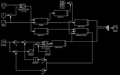
| click me |
|---|
| Click to enlarge. |
I stole the sliding-mode idea from Microchip and Freescale, but in this implementation I have abandoned just about every other aspect from the observers detailed above. Specifically, I don't want to do any coordinate transformations in the fast loop...at all. The way I avoided coordinate transforms when I was crunched for computing power in my first FOC implementation was to use a sine wave generator, which steps through a table of sine values with some given speed. So I'm doing the same thing here, generating the back EMF estimates for phases A, B, and C as a set of three sine waves offset by 120º in the table.
The inputs to the back EMF sine wave generator are the magnitude and the speed, which are each compensated by the sliding-mode feedback with some gains, G1, and G2. The magnitude feedback isn't as critical, but it corrects for variation of the torque constant in the motor model. The speed feedback adjusts how fast a certain magical index steps through the sine table array. This behaves like a phase lock loop, shifting the back EMF until it is in phase with the true back EMF. Don't ask me to explain it in any more detail than that. Here's it starting with a 180º phase offset and locking in:
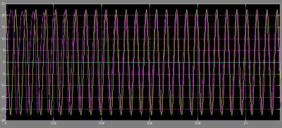 Yellow: Actual back EMF. Purple: Estimated back EMF.
The nice thing about the PLL effect is that it doesn't matter if the feedback is positive or negative. As with the AN1078 method, this observer is immune to sensor noise, applied voltage phase, and variations from the model resistance value. But, it also doesn't mind very much having the model inductance off by a factor of 2:
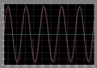
| click me |
|---|
| Yellow: Actual back EMF. Purple: Estimated back EMF. |
It might still need some tweaking to get just the right gains, but at least there is no "phase compensation" table. It also abandons linearity and state space in favor of ease of implementation. The comparisons for the sliding mode observer occur on each phase individually, and in fact only one phase is needed to run the observer. With all three phase currents, an averaging effect should make it work even better. Another interesting possibility is that the table through which the back EMF generator steps need not be a table of sine values. It could very well be an table of measured back EMF values, which should improve the position estimate in the case of trapezoidal EMF motors.
Once again I've created something that I can't really analyze. Time to try implementing it in hardware.
Posted by Shane Colton at 4:10 AM Labels: motor control, sensorless
2 comments:
1.
 shentaJanuary 18, 2014 at 10:18 AMNice work Shane, but under low speed, I would assume your observer can not Lock into the correct angle, due to accumelative integral delay. Dave from TI, is talking about 2nd order IIR filter, which can track position at a very low speed. Have you try that yet? I have also build AN1078, the low pass filter it uses, is nothing more than a delay filter, after each 45d delay, and when revserse, you got the signal of last BEMF... put in plain human words, it delay 180d, reverse it, than it should be something you can use. Well, on theory, yes, you SHOULD be able to use it, however, in reality, it has problem during acceleration, because it does not compensate for the 180d delay you are getting, especially on the hub motor. I am interested in your observer, can you tell us more about it?
Reply
2.
 Shane ColtonFebruary 4, 2014 at 9:14 PMYes, you're right about the behavior at low speed. I think most of the error is from current sensor bias and also voltage "error" (You are driving the voltage, but due to dead time and other nonlinearities it may not be exactly the average value intended. If you use a measured voltage instead, then there could be sensor bias there as well.) So with very well zero-biased current sensors and good mapping from PWM to physical voltage, you can probably operate at extremely low speeds.
The type of filter is an interesting choice. I have used a simple first-order IIR but I have also done simulations with a 2nd-order IIR. It has the advantage of eliminating sensor DC bias errors, but it adds phase offset at low speeds. To eliminate these offsets, you would have to do compensation like in AN1078, but as you point out it then becomes more sensitive to acceleration.
So there are definitely tradeoffs for low-speed operation. I will try to capture them more thoroughly in some documentation that I will post soon.