Index
- BMSBattery S series
- BMSBattery S06S
- S06ST (torque sensor version)
- S06S-BL (Bluetooth version)
- PWM signals
- Phase B current signal
- Throttle
- BMSBattery S06SC
- BMSBattery S12S
- BMSBattery bottle battery controller
- LCD control panel
- Kunteng mobile app
- Bluetooh
- How to open the controller and solder the programming header
- Hardware mods
- Other controllers
- BMSBattery S06P
- Kunteng 18 mosfets motor controller
- Lishui motor controllers
- JinHui motor controllers
- GreenEBikeKit
- Torque speed
- Motor control scheme of S06S controller
- BLDC 6 steps
- PWM schemes
- So, Which PWM Technique is Best? (Part 1)
- So, Which PWM Technique is Best? (Part 2)
- So, Which PWM Technique is Best? (Part 3)
- So, Which PWM Technique is Best? (Part 4)
- So, Which PWM Technique is Best? (Part 5)
- So, Which PWM Technique is Best? (Part 6)
- So, Which PWM Technique is Best? (Part 7)
- PWM control and Dead Time Insertion
- Low inductance motors
- Throttle Control Modes
- Phase angle FOC
- PWM frequency VS motor eRPM
- Sinusoidal Control of BLDCM with Hall Sensors Based
- Self-Learn Hall Sensor Calibration Mode
- STM8S105 Alternatives
- PID algorithm - negative output values
- Regeneration
- FOC
Datasheets and application notes
- STM8S105C6T6
- Endless-sphere.com forum messages
- 2017.04.25 - Initial forum message
- 2017.05.08 - First flash and debug on a dev board
- 2017.05.18 - First code flashing and running
- 2017.05.20 - more new information
- 2017.08.23 - SxxP versus SxxS versus LSW-675
- 2017.09.01 - Trying to figure out an algorithm to automatically adjust ui8_position_correction_value
- 2017.09.02 - How to do FOC on the BMSBattery S06S/Kunteng STM8 motor controllers
- 2017.09.03 - more ideas about zero crossing for FOC
- 2017.09.05 - measuring IQ current and manually adjusting position_correction_value
- 2017.09.15 - our OpenSource firmware efficiency compared to Lishui 12 FET FOC
- 2017.09.19 - measuring motor current
- 2017.10.23 - FOC and no FOC comparison
- 2018.01.10 - How to measure FOC_READ_ID_CURRENT_ANGLE_ADJUST
- 2018.02.20 - Reading motor phase current from the DC link current (shunt)
So, Which PWM Technique is Best? (Part 4)
https://www.ecnmag.com/blog/2012/04/so-which-pwm-technique-best-part-4So, which PWM technique is best? (Part 4)
Tue, 04/10/2012 - 3:27pm by Dave Wilson, Motion Products Evangelist, Texas Instruments
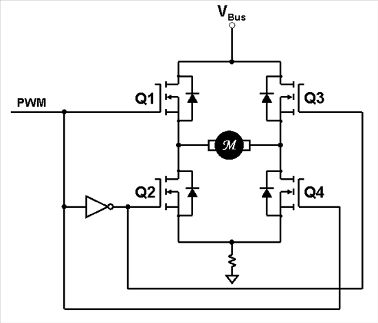
So, which PWM technique is best for your motor control application? Up to now we have investigated three different PWM techniques. Some could regenerate energy back into the DC power supply, and some couldn’t. But they all had one characteristic in common: unipolar voltage waveforms. In other words, for any given PWM period, the motor voltage waveform transitions between Vbus and ground or –Vbus and ground. In this blog, we will investigate the claims of the bipolar PWM technique. For every PWM period, the motor voltage waveform transitions between Vbus and –Vbus, creating a motor voltage waveform amplitude that is twice that of unipolar PWMs. To do this, we will wire the H-Bridge up as shown below.
Do you notice anything missing in the above diagram (besides the implied dead-time circuit between the top and bottom transistors)? How about the fact that there is no longer a forward/reverse signal. With bipolar PWMs, forward and reverse information is encoded in the PWM signal itself. Assuming no load, PWM values over 50 percent duty cycle cause forward motion, and values below 50 percent duty cycle result in reverse motion. For you mechanical engineers out there, this is the electrical equivalent to the hydrostatic continuously variable transmission (CVT). With such a system, you don’t have separate forward and reverse gears. You simply move the stick to control your speed and direction at the same time, with the middle position corresponding to zero speed.
 So, Which PWM Technique is Best? (part 4)- Image 1
The bipolar PWM technique is inherently a 4-quadrant technique. As long as the average applied motor voltage is of the same polarity as the motor’s back-EMF voltage, and it is greater in amplitude than the back-EMF, then the motor will operate in motoring mode. You can watch a simulation of quadrant 1 operation with bipolar PWMs by clicking here. However, if the average applied motor voltage is of the same polarity as the back-EMF, but its amplitude is less than the back-EMF, then the motor will operate in generating mode. You can watch a simulation of quadrant 4 operation of bipolar PWMs by clicking here.
Another advantage of the bipolar PWM technique is that it only requires one PWM signal from your processor (two if the dead-time is generated within the PWM module itself). Assuming that dead-time is provided externally by the FET gate drivers, this means that on a processor with six independent PWMs can drive up to six DC motors using bipolar PWMs!
But perhaps the biggest advantage of bipolar PWMs is the fact that motor current is always flowing through the single shunt resistor, regardless of which state the PWM signal is in. So now that we have continuous visibility to the motor current, the question becomes, “when should the current waveform be sampled?” While I intend to deal with current sampling in greater detail in a later blog, let me just touch briefly on it here. In most cases, you would like to acquire the average motor current as a function of time. But the problem is that the spot on the current waveform which corresponds to the average current value will occur at different times within the PWM cycle, depending on what the duty cycle is. So, we either have to use a timer to trigger the ADC at different times within the PWM waveform depending on the commanded duty cycle, or…
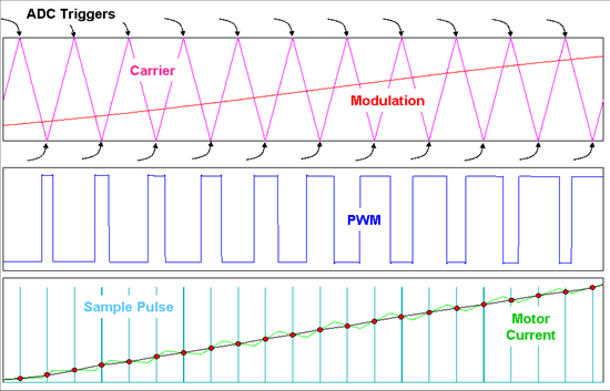
We could use center-aligned PWMs. In most cases, we choose to use center-aligned PWMs because of the harmonic interaction between two separate PWM signals. But in this case, we only have one PWM signal. So why does it help to use center-aligned PWMs? In this case it is how the center-aligned PWMs are created within the PWM module that provides a unique advantage when applied to bipolar PWMs. Referring to the figure below, center-aligned PWMs can be generated by using a triangular counter waveform, where the counter counts up to a maximum modulus value, and then turns around and counts back down to a minimum modulus value, and so on. As the modulation voltage is changed, the PWM pulse width is also changed in such a way that the carrier peaks and valleys occur right in the center of the low pulse width and the high pulse width respectively. If we ignore any delays due to dead-time, we see that the average value of current also occurs right when the carrier reaches a peak or valley! Pretty neat, huh? On the PWM module used on our C2000 processors, ADC triggers can be generated at the counter peaks and valleys, which can then be used to sample the current at the moment the current waveform equals its average value. In fact, with bipolar PWMs, you get two opportunities to sample the motor current within a PWM cycle, which allows you to run your digital current loop at twice the PWM frequency if desired.
 So, Which PWM Technique is Best? (part 4)- Image 2
Another problem that occurs when reconstructing the motor current waveform is that for very narrow pulse widths, the shunt signal only reflects the motor current for a very small period of time, and it may be too short to achieve a reliable reading. However, with bipolar PWMs, if the pulse width for one of the PWM states is too short, you can simply flip to the other PWM state, where the shunt signal will be correspondingly longer! So you are always guaranteed to have at least one interval within each PWM cycle (regardless of the duty-cycle value) where the shunt signal width is wide enough to easily facilitate an accurate reading of the motor current.
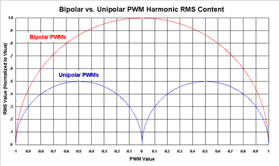
The bipolar PWM technique does however suffer from one noteworthy disadvantage: The motor voltage waveform contains more harmonic content than the unipolar PWM technique does. The graph below compares the normalized RMS content of unipolar and bipolar PWM voltage waveforms (minus the DC component), as a function of sweeping the PWM duty cycle from -1 to +1. Not only do these extra harmonics result in higher current ripple, but they also cause additional heating in the motor. That’s why the bipolar PWM technique is usually restricted to motors with high electrical time constants which can better filter out these harmonics. If the motor does not have a high electrical time constant, then the PWM frequency must often be increased to reduce the current ripple. However, this increases the switching losses in the H-Bridge, which places a limit on how high the PWM frequency can be increased.
 So, Which PWM Technique is Best? (part 4)- Image 3
However, even this disadvantage can be turned into an advantage over unipolar PWMs in some applications. Occasionally you need to slew the motor current very quickly (such as high frequency microstepping on stepper motors). In fact, some applications transition from unipolar PWMs to bipolar PWMs at specific points on the current waveform where you need to slew the current quickly.
A VisSim simulation which compares unipolar and bipolar PWMs on identical motors running with identical loads can be found here. I encourage you to play with this simulation, and see if you can empirically verify the above graph. In our next blog, we will explore one more unipolar PWM technique that can actually double the PWM frequency seen by the motor, while still switching your transistors at the regular PWM frequency. It also provides a springboard into understanding how standard 3-phase sinusoidal PWMs work. Until then...
Keep those motors spinning! :-)