Index
- BMSBattery S series
- BMSBattery S06S
- S06ST (torque sensor version)
- S06S-BL (Bluetooth version)
- PWM signals
- Phase B current signal
- Throttle
- BMSBattery S06SC
- BMSBattery S12S
- BMSBattery bottle battery controller
- LCD control panel
- Kunteng mobile app
- Bluetooh
- How to open the controller and solder the programming header
- Hardware mods
- Other controllers
- BMSBattery S06P
- Kunteng 18 mosfets motor controller
- Lishui motor controllers
- JinHui motor controllers
- GreenEBikeKit
- Torque speed
- Motor control scheme of S06S controller
- BLDC 6 steps
- PWM schemes
- So, Which PWM Technique is Best? (Part 1)
- So, Which PWM Technique is Best? (Part 2)
- So, Which PWM Technique is Best? (Part 3)
- So, Which PWM Technique is Best? (Part 4)
- So, Which PWM Technique is Best? (Part 5)
- So, Which PWM Technique is Best? (Part 6)
- So, Which PWM Technique is Best? (Part 7)
- PWM control and Dead Time Insertion
- Low inductance motors
- Throttle Control Modes
- Phase angle FOC
- PWM frequency VS motor eRPM
- Sinusoidal Control of BLDCM with Hall Sensors Based
- Self-Learn Hall Sensor Calibration Mode
- STM8S105 Alternatives
- PID algorithm - negative output values
- Regeneration
- FOC
Datasheets and application notes
- STM8S105C6T6
- Endless-sphere.com forum messages
- 2017.04.25 - Initial forum message
- 2017.05.08 - First flash and debug on a dev board
- 2017.05.18 - First code flashing and running
- 2017.05.20 - more new information
- 2017.08.23 - SxxP versus SxxS versus LSW-675
- 2017.09.01 - Trying to figure out an algorithm to automatically adjust ui8_position_correction_value
- 2017.09.02 - How to do FOC on the BMSBattery S06S/Kunteng STM8 motor controllers
- 2017.09.03 - more ideas about zero crossing for FOC
- 2017.09.05 - measuring IQ current and manually adjusting position_correction_value
- 2017.09.15 - our OpenSource firmware efficiency compared to Lishui 12 FET FOC
- 2017.09.19 - measuring motor current
- 2017.10.23 - FOC and no FOC comparison
- 2018.01.10 - How to measure FOC_READ_ID_CURRENT_ANGLE_ADJUST
- 2018.02.20 - Reading motor phase current from the DC link current (shunt)
Sensorless - 2011.04.10
http://scolton.blogspot.pt/2011/04/sensorless.htmlSunday, April 10, 2011
Sensorless
I hate making excuses almost as much as I hate Toscanini's, but my project progress and posting frequency has gone way down this semester as a result of having actual work to do just to keep up with 2.007, my class on power electrons, and, oh yeah, PhD qualifier exams, Round 2. (Shout-out to all you MechE controls profs: How about a Segway problem? Eh? You know you want to.)
| click me |
|---|
| Doooooooo it. |
Anyway, whenever it is that I am able to get back to doing real things, I've set a new target on sensorless field-oriented control. The interpolated Hall effect sensor FOC I use now works great, even at low speed, the sensor costs $3 to implement, it's mostly reliable, and it's easy to fix. So of course it's my job now to make it twitchy and unreliable, especially at low speeds, and to eat the $3 cost savings by improving the current sensors.
And there are so many ways to do sensorless control of brushless motors...
| click me |
|---|
| Turnigy Sentilon 100A HV |
One way is just to buy a sensorless controller. Besides being a cop out, sensorless controllers like the one above are designed for voltage-controlled RC airplane duty. They use block commutation - driving two phases and measuring EMF on the third to determine rotor position. So, no field-oriented control, no sine waves, no current limting, and only crude start-up routines. Despite all that, a large enough RC plane ESC can sometimes be made to work well for small vehicles.
| click me |
|---|
| And sometimes not. |
What I'm more interested in is true field-oriented control without position sensors. This means sinusoidal commutation with a high-resolution rotor position estimate, and independent control of the torque-producing current (Iq) and field-augmenting current (Id). With this type of control, all three motor phases are being driven at all times, so there is no opportunity to directly measure back EMF. Thus, a different way of deriving rotor position is required. Here's where the field diverges (lolpun) into several approaches:• Rotor position estimators that measure asymmetric rotor inductance using test pulses or high frequency injection. These have the advantage of working even at zero speed.
• Open-loop back EMF or flux observers, which require a good motor model.
• Closed-loop back EMF or flux observers, which are more forgiving.
There are at least two ways to detect the rotor position of a permanent magnet motor even at a standstill. If the rotor has saliency, its inductance is a function of electrical angle. Internal permanent magnet (IPM) motors are one good example of this, since the flux path through rotor steel changes as a function of angle. But surface permanent magnet (SPM) motors, like the ones I mostly encounter, have more-or-less constant inductance. The magnets themselves have close to the permeability of air, and the steel back-iron is rotationally symmetric.
| click me |
|---|
| A good sensorless algorithm could probably pick up the little magnet-retaining nubs, though... |
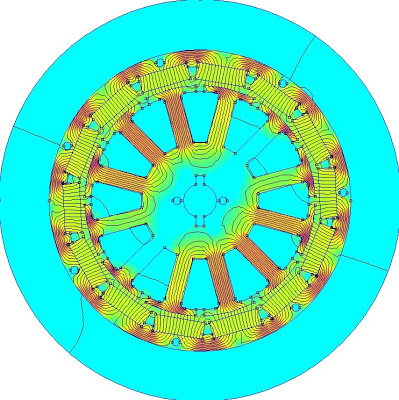
There's another way to statically determine the position of the rotor, which relies only on the fact that motors like this operate stator teeth very near to saturation. The flux density in the most "orange" teeth in the FEMM simulation above is about 1.8T. So, driving current into that tooth's winding would not be able to increase the flux as much in the positive direction as it would in the negative direction. (Also, the rise time would be faster in the positive direction.) A clever algorithm could pick out the rotor position based on this principle.
I don't really want to write a clever algorithm, though. Measuring inductance requires good high-bandwidth current sensing, which I don't currently have, to pick out the rise time in response to a voltage step. Also, this algorithm only applies to start-up unless you use high-frequency injection to measure inductance dynamically while the phases are being driven. I'm sure there are some magic ways to do this that are cleaner than I am imagining (Rainer Nase, I'm looking at you...), but right now it's not something I want to mess this.
Moving on, then, to open-loop observers.
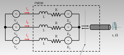
An observer is a control structure that attempts to recreate states which are hidden from direct sensing. Generally, an observer requires some model of the plant, so a good place to start would be a model of a three-phase brushless motor.
| click me |
|---|
| Engineers do it with models. |
It would be nice to know the back EMF, but it's buried inside the black-box PMSM somewhere. Instead, we need to use maths:
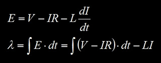
The first maths is just stating KVL for the motor model. V and I can be measured directly, and presumably we know R and L for a given motor, so solving for back EMF, E, shouldn't be a problem. If we know the back EMF, then we know the position of the rotor.
The second maths is an alternative open-loop observer on rotor flux linkage, which is just the integral of back EMF. This has some practical advantage over the first maths. Taking the derivative of the already-noisy current measurement will result in bad things, so even though they are physically equivalent, the smoothing integral formulation of the flux observer is more appealing in a noisy environment. Since rotor flux lines up with the permanent magnets, this also gives rotor position.
The closed-loop observers go one step further.
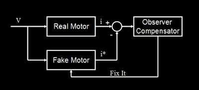
The motor model is only valid if resistance and inductance are known. If the model parameters are off, the estimated states will also be off. A closed-loop observer attempts to correct for modeling error with feedback. Generally speaking, the closed-loop observer goes something like this:1. Input the drive voltage, V, based on the PWM state.
2. Estimate the current, i*, based on the motor model and back EMF estimate.
3. Compare to the measured current, i.
4. Feedback (i - i*) into the observer to modify the back EMF estimate.
| click me |
|---|
| "Fake motor" exists only in software. |
This is less dependent on having perfectly accurate resistance and inductance parameters. The linear version of this, called a Luenberger observer, is detailed in Mevey, Chapter 7. Since I learned pretty much everything I know about brushless motor theory from Mevey's thesis, I would give a lot of weight to his particular explanation.
There is also a slightly different feedback structure that I really like, called a sliding-mode observer. Instead of using the value of (i - i*), it uses only the sign of the error in what is aptly described as a Class D Error Amplifier, switching rapidly between a positive and a negative feedback path. The appeal of this method, covered well in Microchip AN1078, is that the switching structure clearly "eats" the current measurement noise. Right? ...... Right?
Anyway the sliding mode observer structure from AN1078 is the one I am most interested in trying, since it might even work on my existing hardware, crappy current sensors and all. The only question remaining is exactly which current and back EMF are being observed.
Down the rabbit hole of coordinate systems we go...
Motor theory people seem to really like changing coordinate frames. Both the Luenberger observer and the sliding mode observer are most often presented as seeking the stator-frame components of current and back EMF. That is, two orthogonal components (α,β) on a coordinate plane that is tied to the stator, as opposed to (d,q) which is tied to the rotor. In a balanced three-phase system, this is a minimum set of information required to capture the state of the motor. And it makes sense to use this frame for the observed quantities because...
...because...I don't know why. They all seem to get the (α,β) flux or back EMF vector, then go back to rotor angle using an arctan function. Putting an arctan in my fast loop sounds like a horrible idea, and, excess processing power aside, I would like to avoid it if at all possible. So:
Why not observe the back EMF or the rotor flux on each phase? It's easy to do, since there are no coordinate transformations involved. The fast loop can certainly handle the numeric integration and sliding-mode compensator on all three phases. (It would have to do two components plus a coordinate transform and an arctan anyway.) But then how do you get to the rotor angle? Here is where I start digging a brand new rabbit hole...
I can get the rotor angle the same way I do now. All I need are fake Hall effect sensors for my fake motor.
Since I am observing back EMF or flux on each phase, I can easily (with if statements) detect zero crossings and flag a fake Hall effect sensor transition. This can then feed my existing controller, including the sine wave interpolation, with no modification at all. The rotor angle is calculated by the existing interpolation routine with no need for arctan. It's unconventional, which I like, but I really think it will work and it's simpler than what's out there.
So far, I'm ignoring the problem of start-up, the noisy current sensors, and many other practical issues like the fact that I can't yet program my controller wirelessly and it's buried in my scooter... I'll need to solve some of these in the near future before I can really test this out. But it's on the horizon, and now that it's in writing, I have to do it... Posted by Shane Colton at 8:46 PM Labels: 3ph, sensorless
2 comments:
1.
 apullinApril 13, 2011 at 1:57 PMSomehow, you're always working on something that is pertinent to my interests. So, if you could solve it, design it, and have it manufactured in Hong Kong such I can buy it for <$100, that'd be super...
That being said, have you looked at ESC's for cars from the RC realm? There are some sensorless ones that claim they can deliver smooth startup. Any idea if their architectures or startup algorithms are any different from the airplane & heli ESC's? Something like this:
http://www.hobbyking.com/hobbyking/store/uh_viewItem.asp?idProduct=10370
or this: http://www.hobbyking.com/hobbyking/store/uh_viewItem.asp?idProduct=14634
Reply
2.
 Shane ColtonApril 17, 2011 at 5:15 PMI have indeed looked at RC car controllers, including the Hobby King ones you mentioned. I think they are in general built to withstand high current startups a lot more than airplane ESCs. I'm not sure whether they just use more initial current or if they also have a better ramping algorithm.
They're usually 2-4S LiPo, or 6S at most. I'm running 10S and I try to design my controllers for 12S (48V). Also, the RC controllers use block commutation (square wave drive) instead of field-oriented control (with sine wave drive). However, the price is right (not sure I could ever get my controller down to $100...maybe) and I would like to try the big one out on a lower-voltage, higher-current scooter.