Index
- BMSBattery S series
- BMSBattery S06S
- S06ST (torque sensor version)
- S06S-BL (Bluetooth version)
- PWM signals
- Phase B current signal
- Throttle
- BMSBattery S06SC
- BMSBattery S12S
- BMSBattery bottle battery controller
- LCD control panel
- Kunteng mobile app
- Bluetooh
- How to open the controller and solder the programming header
- Hardware mods
- Other controllers
- BMSBattery S06P
- Kunteng 18 mosfets motor controller
- Lishui motor controllers
- JinHui motor controllers
- GreenEBikeKit
- Torque speed
- Motor control scheme of S06S controller
- BLDC 6 steps
- PWM schemes
- So, Which PWM Technique is Best? (Part 1)
- So, Which PWM Technique is Best? (Part 2)
- So, Which PWM Technique is Best? (Part 3)
- So, Which PWM Technique is Best? (Part 4)
- So, Which PWM Technique is Best? (Part 5)
- So, Which PWM Technique is Best? (Part 6)
- So, Which PWM Technique is Best? (Part 7)
- PWM control and Dead Time Insertion
- Low inductance motors
- Throttle Control Modes
- Phase angle FOC
- PWM frequency VS motor eRPM
- Sinusoidal Control of BLDCM with Hall Sensors Based
- Self-Learn Hall Sensor Calibration Mode
- STM8S105 Alternatives
- PID algorithm - negative output values
- Regeneration
- FOC
Datasheets and application notes
- STM8S105C6T6
- Endless-sphere.com forum messages
- 2017.04.25 - Initial forum message
- 2017.05.08 - First flash and debug on a dev board
- 2017.05.18 - First code flashing and running
- 2017.05.20 - more new information
- 2017.08.23 - SxxP versus SxxS versus LSW-675
- 2017.09.01 - Trying to figure out an algorithm to automatically adjust ui8_position_correction_value
- 2017.09.02 - How to do FOC on the BMSBattery S06S/Kunteng STM8 motor controllers
- 2017.09.03 - more ideas about zero crossing for FOC
- 2017.09.05 - measuring IQ current and manually adjusting position_correction_value
- 2017.09.15 - our OpenSource firmware efficiency compared to Lishui 12 FET FOC
- 2017.09.19 - measuring motor current
- 2017.10.23 - FOC and no FOC comparison
- 2018.01.10 - How to measure FOC_READ_ID_CURRENT_ANGLE_ADJUST
- 2018.02.20 - Reading motor phase current from the DC link current (shunt)
So, Which PWM Technique is Best? (Part 7)
https://e2e.ti.com/blogs_/b/motordrivecontrol/archive/2012/04/18/so-which-pwm-technique-is-best-part-7So, Which PWM Technique is Best (part 7)
Dave Wilson, Motion Products Evangelist, Texas Instruments
So, which PWM technique is best for your motor control application? There are certainly plenty of options to choose from, with each one exhibiting unique advantages as well as disadvantages. In this final blog on this topic, let’s conclude with a discussion on regeneration for both DC and AC motors. This has become a much more relevant topic over the last decade due to the popularity of electric and hybrid vehicles. In these applications, regen occurs into a DC bus which is eventually connected to a DC battery bank in the vehicle. But we will see in this blog that we can also regen back into an AC power source, such as the AC power grid.
In part 4 of this series, we investigated the claims of the 4Q Bipolar PWM technique as it applies to DC motors. I made the statement that as long as the applied average voltage from the PWM process is greater than the motor’s back-EMF voltage, AND the two voltages have the same polarity, then the system is operating in motoring mode. Conversely, if the applied average voltage is less than the motor’s back-EMF voltage, and it has the same polarity, then the system is operating in generating mode. It turns out that this rule is not just endemic to bipolar PWMs but applies to all of the four-quadrant PWM techniques we have investigated. But what if the applied average voltage is of the opposite polarity? Also, under what conditions can you regenerate the maximum amount of energy?
To answer these questions, let’s look at a specific example and extrapolate our findings to a general solution. Consider the case below of a brush DC motor powered by an H-Bridge which is connected to a stiff 24V supply. The motor shaft is connected to a dynamometer which is spinning the motor in the reverse direction (negative back-EMF).
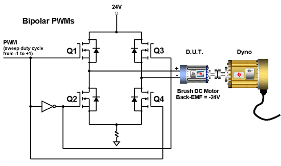
At t = 0, the motor has a back-EMF voltage of -24 volts, and the PWM duty cycle is -1 (Q2 and Q3 are ON 100% of the time). Now, let’s slowly sweep the PWM value from -1 to +1 (Q1 and Q4 ON 100% of the time). A Spice simulation of this scenario has been created, and the resulting average applied motor voltage, as well as the bus power are plotted as shown below. You can download and run the Spice simulation for yourself by clicking on the link here.
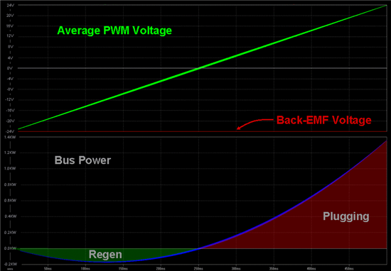
A few interesting observations can be gleaned from this diagram:
1. Since the back-EMF voltage is -24V, the entire PWM range from -1 to 0 will result in an applied average motor voltage which is less in amplitude AND of the same polarity as the back-EMF voltage. Therefore, PWM values from -1 to 0 result in regeneration.
2. The most power regeneration occurs when the applied average motor voltage is -12V. In fact, it turns out that the point of maximum power regeneration always occurs when the applied average motor voltage is equal to half of the back-EMF voltage! If you don’t believe me, try changing the dyno speed in the simulation and see for yourself!
3. When the PWM value reaches 0 (bipolar motor voltage with 50% duty cycle), the bus power also goes to zero, despite the fact that motor current is continuing to increase. Instead of kinetic energy being sent back into the DC bus, it is instead dissipated in the motor windings and the power switches.
4. PWM values from 0 to +1 create an average applied voltage that has an opposite polarity compared to the back-EMF voltage. Therefore, regen cannot occur. Instead the “plugging” region is entered where the kinetic energy is once again dissipated in the motor windings and the power switches. But in the plugging region, the bus voltage is now working in series with the back-EMF voltage to increase the motor current. If left unchecked, the current can reach potentially dangerous levels.
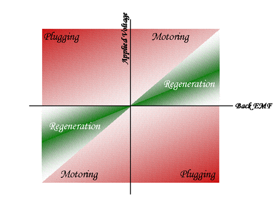
All of these observations can be summarized in the plot below, regardless of which four-quadrant PWM technique you choose. As can be seen, energy flow is controlled by simply controlling the average applied voltage with respect to the back-EMF voltage of the DC motor. (At this point, I should remind you that it is really the average bus current that determines whether regen occurs or not. However, the relationship between applied average voltage to the back-EMF voltage, as well as the type of PWM technique being used, establishes the steady-state condition which will lead to positive or negative bus current.)
The above diagram applies to DC motors. But you are probably asking, “what about AC motors? Does a similar relationship exist here too?” Well, I’m glad you asked. :-) The simple answer is “YES.” However, the back-EMF signal is a sinusoid which changes polarity even under steady-state conditions, so the above diagram does not work with AC motors. Instead, we must focus on the angular relationship between the EMF voltage phasor and the current phasor. The electrical power per phase which corresponds to the shaft power of an AC motor is given as:

where: EMFm and Im are the peak magnitudes of the sinusoidal back-EMF and current waveforms respectively.
q corresponds to the angle between the EMF and current phasors.
From this equation, we can see that for a given current magnitude and EMF voltage, maximum power transfer occurs when q equals zero or pi. From the perspective of the back-EMF voltage, these conditions also result in unity power factor. It can be shown that these two operating conditions also result in maximum torque per amp (MTPA) on the motor. So we would like to place the current phasor on the same axis as the back-EMF phasor. For the case where q = 0, power is positive, meaning that power is being transferred to the motor. When q = pi, the power is negative, meaning that power is being transferred from the motor. These two cases are illustrated in the diagram below.
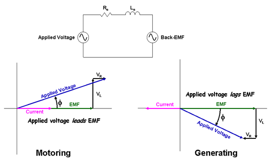
The per-phase circuit of an AC motor winding is shown at the top of the diagram. You can control whether you operate in motoring or generating mode by simply causing the current phasor to be in-phase or 180 degrees out of phase with the back-EMF phasor. The real and imaginary values of the voltage phasor you need to apply to the H-Bridge in order to achieve this are calculated by simply adding up the voltage drops around the per-phase circuit:

To explore this concept a bit further, a Spice model was created of a single-phase AC motor connected to an H-Bridge and driven with bipolar PWMs. You can download the simulation here. The schematic is shown below.
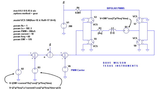
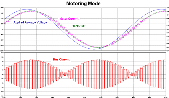
As an example, let’s assume that the desired value of current is positive 10 amps (motoring mode). The real and imaginary components of the applied voltage waveform required to create a 10A phasor exactly in phase with the EMF phasor are calculated by using the equations shown above for dependent sources B2 and B3. The resulting sinusoidal waveforms are summed together algebraically and then scaled by the bus voltage to achieve a modulation range of +/-1. The plots below show that the current waveform is indeed exactly in phase with the EMF, and the average bus current is positive.
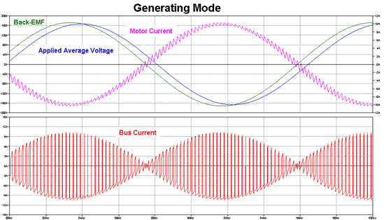
Now let’s change the desired current to be negative 10 amps (generating mode) and rerun the simulation. The resulting waveforms are again shown below. In this case, the current waveform is 180 degrees out-of-phase with the EMF waveform, and the average bus current is now negative.
You may have noticed the interesting value I selected for the motor’s back-EMF voltage. 170V just happens to be the peak value for residential AC voltage in the United States. Remember, every motor is a generator, and every generator is a motor. So if you connect a wall socket to the output of an H-Bridge through a series inductor, you can think of the power grid as a very large motor running at a very constant speed. By knowing the inductor’s value along with its parasitic resistance, you can sync up to the grid and calculate the waveform you need to modulate onto the H-Bridge so as to control power flow to or from the grid. In many cases, this DC bus is connected to another inverter on the back end which is controlling a motor. By monitoring the voltage level of the DC bus and comparing it to a desired value, you can adjust the modulation on the H-Bridge to either pump-up the bus from the grid (the motor is motoring), or to lower the bus voltage by throwing excess energy back on to the AC grid (the motor is generating). And by aligning the current phasor with the grid voltage as discussed above, you can achieve almost perfect unity power factor, regardless of which direction the energy is flowing! Pretty neat huh?
At this point you may be asking if the above power control technique can be extended to three phase systems by using a three-phase inverter instead of an H-Bridge. The answer is a resounding “YES!” In fact, you have two options you can use to accomplish this, and I have seen systems that have been built using both techniques:
1. The first option is to simply extrapolate the technique discussed above to three separate control problems. In other words, connect a series inductor between each phase of the power grid and each phase of the inverter, and control each half bridge in the inverter independently as described above. This technique has the advantage of working on three phase systems even if they are unbalanced, since the calculations for each phase are handled independently.
2. Treat all three phases as a single control problem, and use Field Oriented Control (FOC) techniques to align the AC grid current space vector to be on the same axis as the AC grid voltage space vector. This approach has the advantage of simplicity since it requires only one control algorithm, plus it reuses the same routines that are common library calls for FOC.
Four-quadrant-control simulation models have been built up for both single-phase and three-phase systems and will be presented in a later blog. The three-phase simulation uses the second approach mentioned above, so it makes sense to cover FOC before presenting this solution.
So, there you have it! <Whew>! Sorry for the lengthy blog, but I wanted to make a sprint for the finish line to keep this from spilling into “Part 8”! And believe it or not, we still didn’t cover all of the PWM modulation techniques. For example, we didn’t talk about discontinuous PWMs, which derive their name from the fact that the motor current can transition from conducting to non-conducting within a PWM cycle at low modulation indices. However, this is not a very popular technique since the system dynamics can change abruptly as the motor current transitions between discontinuous and continuous modes. Also, we just barely scratched the surface on Space Vector Modulation, which is rapidly becoming the most popular modulation technique for AC motors. This technique is so prevalent however, that I think it deserves special treatment in a future blog series. But hopefully we covered enough PWM techniques to give you a large palate of solutions to choose from for your next motor control design.
Please keep in mind that ALL the techniques we discussed in this series are possible with the PWM module on our C2000 embedded processors. In many cases we have created application notes and reference designs that can help you set up the PWM module to accomplish a specific type of modulation. Thanks for your interest in this topic, and by all means…