Index
- BMSBattery S series
- BMSBattery S06S
- S06ST (torque sensor version)
- S06S-BL (Bluetooth version)
- PWM signals
- Phase B current signal
- Throttle
- BMSBattery S06SC
- BMSBattery S12S
- BMSBattery bottle battery controller
- LCD control panel
- Kunteng mobile app
- Bluetooh
- How to open the controller and solder the programming header
- Hardware mods
- Other controllers
- BMSBattery S06P
- Kunteng 18 mosfets motor controller
- Lishui motor controllers
- JinHui motor controllers
- GreenEBikeKit
- Torque speed
- Motor control scheme of S06S controller
- BLDC 6 steps
- PWM schemes
- So, Which PWM Technique is Best? (Part 1)
- So, Which PWM Technique is Best? (Part 2)
- So, Which PWM Technique is Best? (Part 3)
- So, Which PWM Technique is Best? (Part 4)
- So, Which PWM Technique is Best? (Part 5)
- So, Which PWM Technique is Best? (Part 6)
- So, Which PWM Technique is Best? (Part 7)
- PWM control and Dead Time Insertion
- Low inductance motors
- Throttle Control Modes
- Phase angle FOC
- PWM frequency VS motor eRPM
- Sinusoidal Control of BLDCM with Hall Sensors Based
- Self-Learn Hall Sensor Calibration Mode
- STM8S105 Alternatives
- PID algorithm - negative output values
- Regeneration
- FOC
Datasheets and application notes
- STM8S105C6T6
- Endless-sphere.com forum messages
- 2017.04.25 - Initial forum message
- 2017.05.08 - First flash and debug on a dev board
- 2017.05.18 - First code flashing and running
- 2017.05.20 - more new information
- 2017.08.23 - SxxP versus SxxS versus LSW-675
- 2017.09.01 - Trying to figure out an algorithm to automatically adjust ui8_position_correction_value
- 2017.09.02 - How to do FOC on the BMSBattery S06S/Kunteng STM8 motor controllers
- 2017.09.03 - more ideas about zero crossing for FOC
- 2017.09.05 - measuring IQ current and manually adjusting position_correction_value
- 2017.09.15 - our OpenSource firmware efficiency compared to Lishui 12 FET FOC
- 2017.09.19 - measuring motor current
- 2017.10.23 - FOC and no FOC comparison
- 2018.01.10 - How to measure FOC_READ_ID_CURRENT_ANGLE_ADJUST
- 2018.02.20 - Reading motor phase current from the DC link current (shunt)
Self-Learn Hall Sensor Calibration Mode
http://www.etotheipiplusone.net/?p=2373The magic green (may be other colors on your specific variant) wire is usually embedded in the forest of wires these things come with. It’s terminated in a small snap-on connector.
Basically, the controller recognizes that this pin is connected when you first power on. It attempts to run the motor sensorlessly and captures what the Hall sensor waveform looks like, saves it to memory, and then when throttle is commanded, it will power the phases according to what state the motor is in and what it ‘saw’. You can indicate that the motor is being learned in the wrong direction (by unplugging and reconnecting the self-learn wire once) and it will reverse the direction and record the states again, saving that and associating that direction with “forward”.
----
How to Tame Your Shady Chinese e-Bike Controller: Self-Learn Hall Sensor Calibration Mode
Saturday, November 3rd, 2012 @ 1:33 | Beyond UnboxingIn my continued quest to discover new ways to EV on the cheap for builders, I’ve worked on demystifying several types of sketchy Chinese motor controllers to assess how applicable they are to little electric rideable things. My most recent favorite has been the “Jasontroller” electric bike controller. Like every other generic Chinese electromechanical product – it has no actual real name (the “Jason” moniker started as an inside joke in our EV contingency and is a bit of a satire on companies like Kelly), no well-known company with customer support to back it, nor any real details about hookup and operation.
(Scheduled plug: By the way, I still have alot of stuff for sale!)
Do you guys, like, know eachother?
Most of these generic Chinese e-bike controllers are pretty much the same functionality and firmware-wise, but what appealed to me specifically regarding that model is that it has a reasonably competent sensorless mode, complete with motor current limiting, for driving inertial loads, specifically vehicles. R/C type aircraft and car ESCs just aren’t the same in this regard; more details can be found in my Instructable on the matter. I’ve found that the sensorless mode on the Jasontroller is fine enough for scooters (and their design target, electric bikes) because you can always move just a little to avoid the zero-speed condition that sensorless is worst at. For things where you don’t get to push off, like Chibikart and DPRC, they’re somewhat hopeless. The algorithm is very simplistic and typical of ‘block’ commutation startup – just open-loop power the motor phases until a valid phase voltage waveform is detected. Usually in the case of an inertial load, the slow bobbing of the rotor is not strong enough to cause any significant motion and the startup fails. In the case of a cheap R/C type controller with no current limiting, the controller explodes from having to power a stalled motor.
While the controllers usually do have a Hall sensor connection, the hard part is adding sensors to the motor itself and connecting them correctly. In the past, I’ve accomplished this by both putting them inside the motor as well as outside on 3D printed mounts and cute sensor holder rings. Then, explaining the process of lining up the 3 sensor bits with the 6 internal states of the 3 phase motor usually takes at least half an hour and much confusion – without knowing the way the motor was wound (i.e. you didn’t wind it), there’s 12 possible ways to hook up motors and sensors and some times you have to brute force them all before finding the right one. Additionally, sensors aren’t optimal at anything except low speed anyway because they suffer from hysteresis-induced timing lag.
Optimally, you’d have a controller that uses the Hall sensor feedback just to kick off. Even if the sensor combo was total bullshit, actively driving the motor in one direction and getting some kind of positive position change is enough to begin ramping the motor sensorlessly up to speed.
What I’ve been kind of hiding is that many of the latest generation e-bike controllers, including the Jasontroller (I have enough of an emotional connection with the thing to name it), has this exact functionality. I’ve never explored it until recently when curiosity got the best of me, and I think this is a total boon for everyone who is building small EVs. It is now my goal to explain how the mode is used and what its limits are. There appears to be some confusion on how the mode is used (example and another), and as a result I haven’t seen it frequently mentioned.
We begin with a picture of the rear of a Jasontroller, where the mysterious Chinese sticker is located.
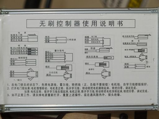
For your entertainment, I’ve fansubbed the Jasontroller below. I’m not gonna claim perfection with my several-versions-out-of-date Chinese language drivers, but hey, who else is gonna give you an English manual?
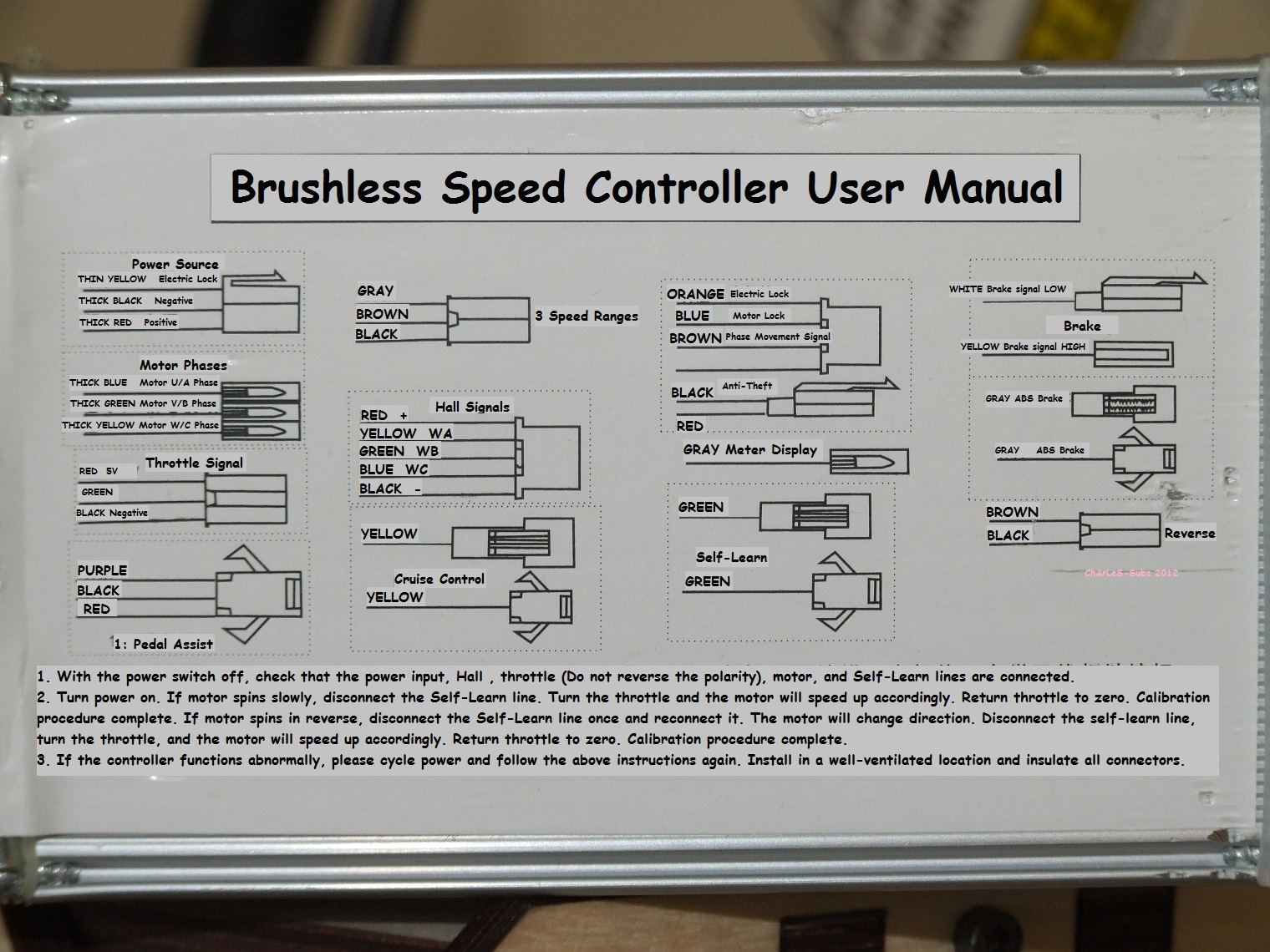
All of the Chinese e-bike controllers you can find are probably generally wired the same way. The funny thing is, as amusing as these devices are to me and many other EV hackers, I’m willing to bet that literally millions of people use them on a day to day basis and find them nothing too ordinary. These are generic replacement controllers for electric bicycles, moped, and scooters made and used by the millions in China. To people who have one of those things, it’s like changing windshield wipers or something.
Take note of the “Self Learn” wire in the lower right. The instructions on the bottom are basically how to use the self-calibration mode of the controller.
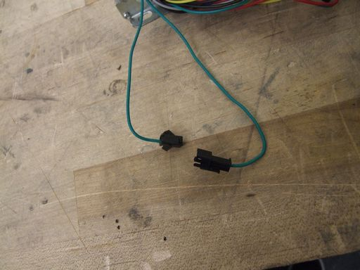
The magic green (may be other colors on your specific variant) wire is usually embedded in the forest of wires these things come with. It’s terminated in a small snap-on connector.
Basically, the controller recognizes that this pin is connected when you first power on. It attempts to run the motor sensorlessly and captures what the Hall sensor waveform looks like, saves it to memory, and then when throttle is commanded, it will power the phases according to what state the motor is in and what it ‘saw’. You can indicate that the motor is being learned in the wrong direction (by unplugging and reconnecting the self-learn wire once) and it will reverse the direction and record the states again, saving that and associating that direction with “forward”.
Nifty. That’s so much software I can’t imagine ever doing it myself. Luckily, some smart Chinese guy has figured it out (and probably got pirated).
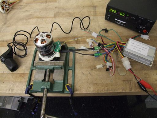
Here’s my Rig of Science that I set up. A 63mm outrunner with my custom Hall holder rig, externally adjustable so I can try and confuse the Jasontroller. The jumper wires that connected the sensor board to the controller was also rearrangeable. Basically, I wanted to see how much bullshit I can feed it and still have the thing work.
The process was basically to train it on a specific sensor arrangement, then swap the sensor combination around and move the board such that the timing is terribly off, and combinations thereof.
What I found was the following:
• If sensors are present and the controller hasn’t been trained before, it will use the factory programmed motor state model.
• The sensors must be 120 or 60 degree space electrically – if there is significant inequality in the spacing, the process incrementally gets worse and worse with spacing error until it just errors out.
• If the sensors are incorrect (do not result in continuous motion) or throw an error for any reason, it will automatically try to switch to sensorless mode.
• Once “trained” for a specific sensor arrangement, it will retain that and use it for any other motor it is connected to until trained otherwise, pursuant to the above rule.
• The sensors are only used for low-speed and stall conditions. There is an audible transition to sensorless mode – the motor sounds “smoother”, lacking the hard-switched sound of the sensored mode.
• Sensored mode does not bypass the internal hardware “speed limit” as a result – the processor is still only capable of running the motor to a relatively modest speed.
There were moments where I got the controller “stuck” in sensored mode, but I can’t consistently replicate the problem. It seems to happen only when the sensors are horrifically off-timing that, I assume, the sensorless algorithm cannot lock in, but why it doesn’t just ditch the sensors at that point is not known to me.
Additionally, another weird symptom that happened several times but I cannot replicate reliably is that if only 2 sensor wires are swapped, it catches on and figures the problem out. The first start is false and runs sensorlessly, but the next start is properly adapted to the new sensor arrangement.
The fuck? Are these things actually sentient and just messing with me instead of vice versa?
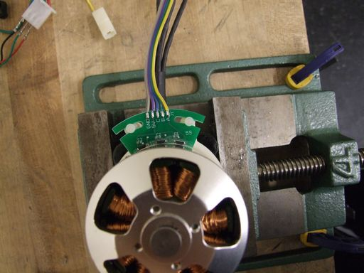
Basically, what I found is that if you line up any sensor with a slot (placed in the middle), the controller will figure it out just fine. For any sensor over a slot, there’s a valid combination that will result in motion, maybe not in the intended direction (but that is what the “reverse learn” switch is for, right?). In the above picture, the rightmost sensor is centered over a slot. I don’t have any info on how this motor wound, so which slot it is is completely not known!
If a sensor is not centered in a slot, then the startup gets rougher and rougher with increasing error until it just switches to sensorless. The transition between sensored and sensorless mode also becomes less smooth.
summary
Here’s a video where I demonstrate how to use the auto-calibration as well as illustrating what happens if a sensor is not located over one slot.
conclusion
Suddenly, the Jasontrollers have become alot more favorable to me. I’ve had a few of them die running all-sensorless into an R/C type outrunner because the current limiting circuit is just not fast enough for those motors, which are generally super-low inductance (current changes very quickly).
Not even Kelly controllers can do this sensor auto-recognition thing right now, and they are currently my go-to for when someone asks me what controller to use for their brushless setup. Calibrating sensors and adjusting timing is one of the worst “black box” magic processes that people have to do, and they matter alot in having smooth vehicle operation.
This neat little feature will save alot of time and effort in vehicle construction. All you really need now is a way to mount sensors to the motor.While I now favor external sensors for outrunners due to their ease of adjustment, the controllers having an automatic sensorless switchover after a certain speed means that embedding sensors in the middle of a slot (inside the motor, by taking it apart) is completely reasonable. This would be an option for people who do not have, or want to make, an external sensor-holding jiggie thing.
I’m probably going to try throwing Halls in DPRC‘s 50mm outrunners in order to truly test this hypothesis under load.
Of course, now I also really want to start selling these sensor holders and boards. Perhaps that will be a product line parallel to RageBridge…
Seeds for your melon
In conclusion,
Why should I go to the length of adding sensors to my motor to use this feature?
Most commercial sensorless motor controllers usually fail at zero and low speed because they depend on having a voltage feedback from the motors to determine rotor position, only possible with continuous motor motion. This means you have to be moving before you can move. While this is okay for, say, scooters and bikes because it is totally reasonable to push off with a foot before hitting the throttle, the same is not true of go-karts, robots, wheelchairs, etc. which you cannot really push off without compromising the function of the vehicle. These MUST have a “zero speed” torque on demand.
What should the motor and sensor arrangement be?
The sensors should be spaced 120 or 60 electrical-degrees (both industry standards), mostly because they divide equally into 360 degrees. Incorrect spacing will probably just result in the controller bailing out to sensorless mode anyway. The way to tell is if the motor has very little startup torque or just twitches helplessly. One sensor should be aligned with 1 slot between the windings on the stator and the controller will be able to figure out the rest. This is true for a standard 12-tooth stator with fractional magnet to slot ratio, anyway – other motors are currently not determined. If the sensor is not aligned with the slot, the startup and switchover transition become rough and rougher with positioning error.
Is this really simpler than running a normal, all-sensor-commutated controller like a Kelly?
Oh hell yes. There is no more playing the keep-it-change-it-flip-it game with sensor vs. phase combinations.
So, simpler, and I believe potentially better. Hall sensors introduce significant timing lag at higher speeds, and the optimal sensor position also changes with speed and load. Having the sensors there only for startup solves the low end torque issue, while driving the motor sensorlessly at high speeds effectively means you drive the motor more according to how it wants to be driven at a given speed and current draw.
Note that your shady-ass generic Chinese e-bike controller may be different. I can only account for the controllers retailed by “bobzhangxu” on eBay at the moment. However,

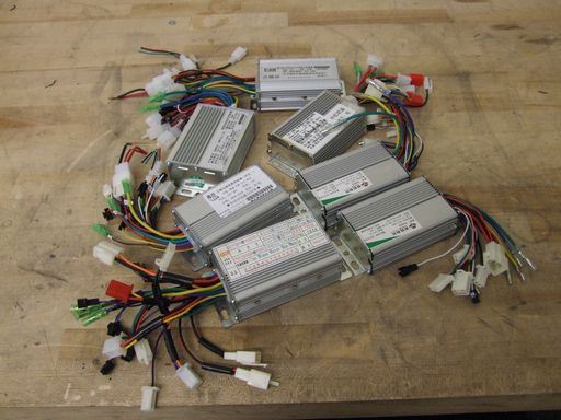
That lead image. Be prepared for a massive Beyond Unboxing post in the next few days where I will attempt to catalog several different shady e-bike controllers and see which ones can perform this training routine! I literally went on eBay and bought 1 of every controller that was under $30 with free shipping or under $40 with shipping. There are 7 in total. The intention is to make an index like my copier motors spreadsheet.