Index
- BMSBattery S series
- BMSBattery S06S
- S06ST (torque sensor version)
- S06S-BL (Bluetooth version)
- PWM signals
- Phase B current signal
- Throttle
- BMSBattery S06SC
- BMSBattery S12S
- BMSBattery bottle battery controller
- LCD control panel
- Kunteng mobile app
- Bluetooh
- How to open the controller and solder the programming header
- Hardware mods
- Other controllers
- BMSBattery S06P
- Kunteng 18 mosfets motor controller
- Lishui motor controllers
- JinHui motor controllers
- GreenEBikeKit
- Torque speed
- Motor control scheme of S06S controller
- BLDC 6 steps
- PWM schemes
- So, Which PWM Technique is Best? (Part 1)
- So, Which PWM Technique is Best? (Part 2)
- So, Which PWM Technique is Best? (Part 3)
- So, Which PWM Technique is Best? (Part 4)
- So, Which PWM Technique is Best? (Part 5)
- So, Which PWM Technique is Best? (Part 6)
- So, Which PWM Technique is Best? (Part 7)
- PWM control and Dead Time Insertion
- Low inductance motors
- Throttle Control Modes
- Phase angle FOC
- PWM frequency VS motor eRPM
- Sinusoidal Control of BLDCM with Hall Sensors Based
- Self-Learn Hall Sensor Calibration Mode
- STM8S105 Alternatives
- PID algorithm - negative output values
- Regeneration
- FOC
Datasheets and application notes
- STM8S105C6T6
- Endless-sphere.com forum messages
- 2017.04.25 - Initial forum message
- 2017.05.08 - First flash and debug on a dev board
- 2017.05.18 - First code flashing and running
- 2017.05.20 - more new information
- 2017.08.23 - SxxP versus SxxS versus LSW-675
- 2017.09.01 - Trying to figure out an algorithm to automatically adjust ui8_position_correction_value
- 2017.09.02 - How to do FOC on the BMSBattery S06S/Kunteng STM8 motor controllers
- 2017.09.03 - more ideas about zero crossing for FOC
- 2017.09.05 - measuring IQ current and manually adjusting position_correction_value
- 2017.09.15 - our OpenSource firmware efficiency compared to Lishui 12 FET FOC
- 2017.09.19 - measuring motor current
- 2017.10.23 - FOC and no FOC comparison
- 2018.01.10 - How to measure FOC_READ_ID_CURRENT_ANGLE_ADJUST
- 2018.02.20 - Reading motor phase current from the DC link current (shunt)
2017.09.01 - Trying to figure out an algorithm to automatically adjust ui8_position_correction_value
Trying to figure out an algorithm to automatically adjust ui8_position_correction_value
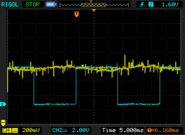
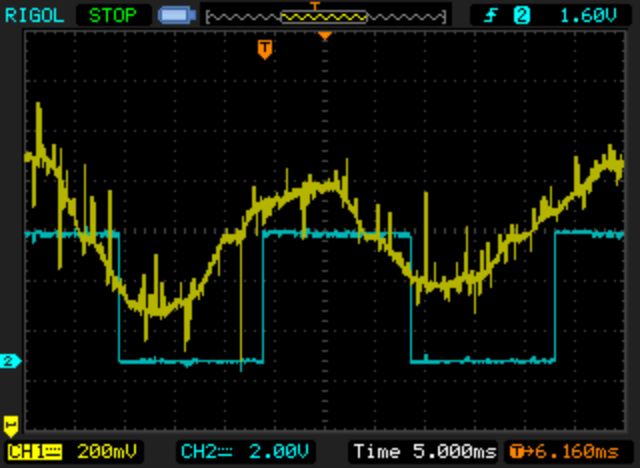
The next oscilloscope screenshots were taken when the motor had a constant PWM duty_cycle value. Blue line represents hall sensors signal (at every 180º and not at 60º). Yellow line is the phase B current signal.
I sent commands by UART, to increase or decrease ui8_position_correction_value and saw the results when this value is above and bellow the correct value.
I repeated this test with other different PWM duty_cycle values/motor speeds and got similar results.
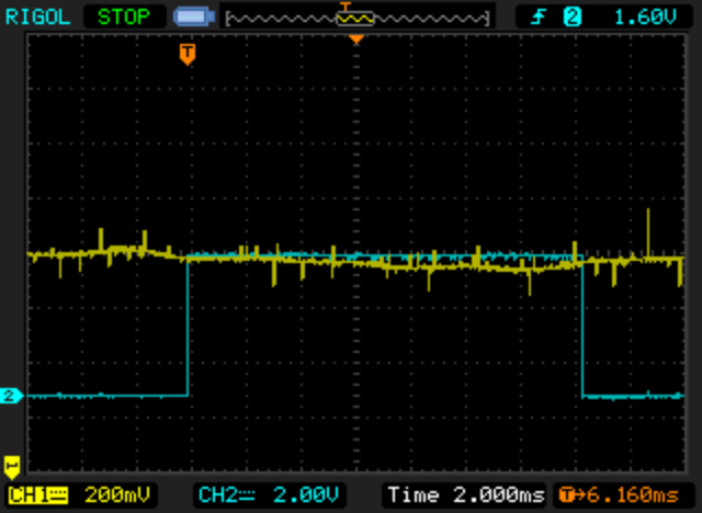
ui8_position_correction_value above value
As we can see, if we look at negative to positive transition of blue line, the current is negative (lower than half of max amplitude). The higher the ui8_position_correction_value, the higher amplitude of the sinewave and also the time difference between the transition of the blue line and zero cross of the yellow line. In this situation, the motor made a lot of vibrations, noise and was using to much current.
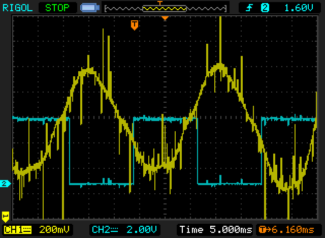
ui8_position_correction_value bellow
At the negative to positive transition of blue line, the current is now positive (see that the current sinewave is now inverted!). The lower the ui8_position_correction_value, the higher amplitude of the sinewave and also the time difference between the transition of the blue line and zero cross of the yellow line. In this situation, the motor made a lot of vibrations, noise and was using to much current.
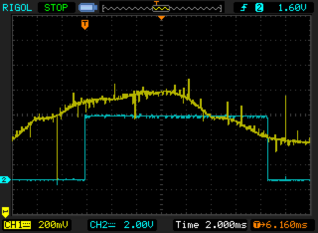
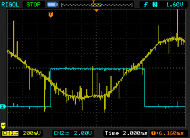
ui8_position_correction_value best value
At the negative to positive transition of blue line, the current is almost zero as also the time difference to the zero cross of the yellow line. In this situation, the motor was quiet, didn't make vibrations and was using very few current.