Index
- BMSBattery S series
- BMSBattery S06S
- S06ST (torque sensor version)
- S06S-BL (Bluetooth version)
- PWM signals
- Phase B current signal
- Throttle
- BMSBattery S06SC
- BMSBattery S12S
- BMSBattery bottle battery controller
- LCD control panel
- Kunteng mobile app
- Bluetooh
- How to open the controller and solder the programming header
- Hardware mods
- Other controllers
- BMSBattery S06P
- Kunteng 18 mosfets motor controller
- Lishui motor controllers
- JinHui motor controllers
- GreenEBikeKit
- Torque speed
- Motor control scheme of S06S controller
- BLDC 6 steps
- PWM schemes
- So, Which PWM Technique is Best? (Part 1)
- So, Which PWM Technique is Best? (Part 2)
- So, Which PWM Technique is Best? (Part 3)
- So, Which PWM Technique is Best? (Part 4)
- So, Which PWM Technique is Best? (Part 5)
- So, Which PWM Technique is Best? (Part 6)
- So, Which PWM Technique is Best? (Part 7)
- PWM control and Dead Time Insertion
- Low inductance motors
- Throttle Control Modes
- Phase angle FOC
- PWM frequency VS motor eRPM
- Sinusoidal Control of BLDCM with Hall Sensors Based
- Self-Learn Hall Sensor Calibration Mode
- STM8S105 Alternatives
- PID algorithm - negative output values
- Regeneration
- FOC
Datasheets and application notes
- STM8S105C6T6
- Endless-sphere.com forum messages
- 2017.04.25 - Initial forum message
- 2017.05.08 - First flash and debug on a dev board
- 2017.05.18 - First code flashing and running
- 2017.05.20 - more new information
- 2017.08.23 - SxxP versus SxxS versus LSW-675
- 2017.09.01 - Trying to figure out an algorithm to automatically adjust ui8_position_correction_value
- 2017.09.02 - How to do FOC on the BMSBattery S06S/Kunteng STM8 motor controllers
- 2017.09.03 - more ideas about zero crossing for FOC
- 2017.09.05 - measuring IQ current and manually adjusting position_correction_value
- 2017.09.15 - our OpenSource firmware efficiency compared to Lishui 12 FET FOC
- 2017.09.19 - measuring motor current
- 2017.10.23 - FOC and no FOC comparison
- 2018.01.10 - How to measure FOC_READ_ID_CURRENT_ANGLE_ADJUST
- 2018.02.20 - Reading motor phase current from the DC link current (shunt)
2017.05.20 - more new information
New information I have:STM8S105C6T6
• pin 2: resistor 2200R and a capacitor to GND. This pin goes to blue wire of undocumented connector with 2 wires (blue and black(GND))
• pin 3: resistor 2200R and a capacitor to GND. Resistor 10k to VCC. This pin goes to a header pin that is not wired
• pin 10: through one resistor, goes to BRAKE wire
• pin 15: ?? goes to a big diode..
• pin 16: goes to pin 7 LM358 (shunt current)
• pin 17: goes to pin output of ACS711 (phase B current)
Components:
• LM317 (voltage regulator): outputs 14.8V for the mosfet drivers
• 78L05 (voltage regulator): outputs 5V for the VCC
• LM358 (dual op-amp):
◇ pin7: outputs a value from shunt current (motor total current)
▪ 1.63V when motor is stopped (zero current)
◇ pin1: always at 5V. Seems it is not used and is connected to 5V with a resistor
• ACS711 (hall effect current sensor):
◇ output pin goes through a resistor (and a capacitor to ground) to pin STM8S105C6T6 pin 17 PB5/AIN5. This measures a motor phase B current (green phase wire)
▪ 2.5V when motor is stopped (zero current)
◇ fault pin is not used and is connected with a resistor to 5V
Possible motor control scheme
his cheap controllers are a 2nd generation. The first generation like BMSBAttery KU63 did only 6 step and had a shunt to measure motor total current, so no FOC nor current in phase +90º with rotor that is one of the main objectives of FOC.
The 2nd generation controllers, costs only 22€ but added a current sensor ACS712 in ne phase. Now the wave forms are sinusoidal and I think they look at the phase current to make it in +90º in phase with rotor, achieving the most important objective of FOC that is keep the motor rotating using the less energy possible (that will also result in more silent motor) -- amazing for a controller that came inside a metal box and water prof and just by 22€. It uses hall sensors only for track motor rotor position.
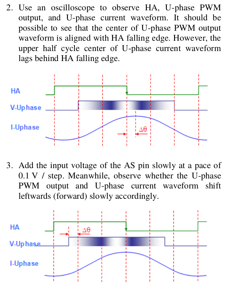
Explanation example of AN-8201 FCM8201 Three-Phase Sine-Wave BLDC Motor Controller document:
At 2., the middle HA is where motor flux is and the I phase current must be at 90º after, but as seen, there is a delta teta added to the point of 90º (that point is at end of positive value of HA).
At 3., the motor phase voltage (that we control) we advance delta teta and the result is the phase current will now be at 90º of middle HA (flux) -- this is the point where the motor will have more torque per amp used, the most efficient point: