Index
- BMSBattery S series
- BMSBattery S06S
- S06ST (torque sensor version)
- S06S-BL (Bluetooth version)
- PWM signals
- Phase B current signal
- Throttle
- BMSBattery S06SC
- BMSBattery S12S
- BMSBattery bottle battery controller
- LCD control panel
- Kunteng mobile app
- Bluetooh
- How to open the controller and solder the programming header
- Hardware mods
- Other controllers
- BMSBattery S06P
- Kunteng 18 mosfets motor controller
- Lishui motor controllers
- JinHui motor controllers
- GreenEBikeKit
- Torque speed
- Motor control scheme of S06S controller
- BLDC 6 steps
- PWM schemes
- So, Which PWM Technique is Best? (Part 1)
- So, Which PWM Technique is Best? (Part 2)
- So, Which PWM Technique is Best? (Part 3)
- So, Which PWM Technique is Best? (Part 4)
- So, Which PWM Technique is Best? (Part 5)
- So, Which PWM Technique is Best? (Part 6)
- So, Which PWM Technique is Best? (Part 7)
- PWM control and Dead Time Insertion
- Low inductance motors
- Throttle Control Modes
- Phase angle FOC
- PWM frequency VS motor eRPM
- Sinusoidal Control of BLDCM with Hall Sensors Based
- Self-Learn Hall Sensor Calibration Mode
- STM8S105 Alternatives
- PID algorithm - negative output values
- Regeneration
- FOC
Datasheets and application notes
- STM8S105C6T6
- Endless-sphere.com forum messages
- 2017.04.25 - Initial forum message
- 2017.05.08 - First flash and debug on a dev board
- 2017.05.18 - First code flashing and running
- 2017.05.20 - more new information
- 2017.08.23 - SxxP versus SxxS versus LSW-675
- 2017.09.01 - Trying to figure out an algorithm to automatically adjust ui8_position_correction_value
- 2017.09.02 - How to do FOC on the BMSBattery S06S/Kunteng STM8 motor controllers
- 2017.09.03 - more ideas about zero crossing for FOC
- 2017.09.05 - measuring IQ current and manually adjusting position_correction_value
- 2017.09.15 - our OpenSource firmware efficiency compared to Lishui 12 FET FOC
- 2017.09.19 - measuring motor current
- 2017.10.23 - FOC and no FOC comparison
- 2018.01.10 - How to measure FOC_READ_ID_CURRENT_ANGLE_ADJUST
- 2018.02.20 - Reading motor phase current from the DC link current (shunt)
So, Which PWM Technique is Best? (Part 6)
https://www.ecnmag.com/blog/2012/04/so-which-pwm-technique-best-part-6So, which PWM technique is best? (Part 6)
Tue, 04/17/2012 - 9:25am 1 Comment by Dave Wilson, Motion Products Evangelist, Texas Instruments
Deeper Insights

The DC/DC Book Of Knowledge

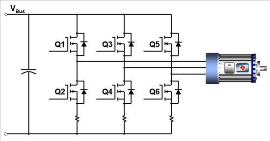
 Dave WilsonSo, which PWM technique is best for your motor control application? Hopefully by now you have seen just how versatile the PWM process can be, and how subtle changes in this process can have a dramatic effect on motor performance. In the previous blogs on this topic, I have only discussed the techniques as they apply to DC motors in an H-Bridge. But in this blog, let’s extend our discussion to multi-phase machines. To apply these techniques to a three-phase inverter, all we have to do is add one more half-bridge, as shown below.
Now we have a topology that can drive AC induction motors, PM Synchronous motors, IPM motors and BLDC motors. However, the PWM technique that we choose will be a function of the type of motor we use. For BLDC motors, we can think of the above three-phase inverter as a combination of three separate H-Bridges: Q1, Q2, Q3, Q4, or Q3, Q4, Q5 Q6, or Q1, Q2, Q5, Q6. To commutate a BLDC motor, we will use only one of these three H-Bridge configurations at any given time. Which H-Bridge combination is selected is based on which two phases we want to drive, and which phase we want to turn off for each commutation interval. As a result, all of the PWM topologies we discussed on brush DC motors in an H-Bridge also apply to BLDC motors.
 Half bridge
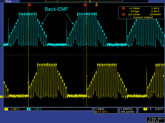
An additional constraint for selecting a PWM topology with BLDC motors occurs when you want to control the motor in sensorless mode by monitoring the motor’s back-EMF. In most cases, we want to measure the back-EMF voltage on the unpowered phase with respect to the motor’s internal neutral node. An example scope shot showing two of the three motor phase voltage waveforms under the condition of 2Q Unipolar PWMs is shown below. As seen in the diagram, the back-EMF signal only appears when that particular phase is unpowered AND the PWM is in the ON state. Depending on the ADC used to sample the back-EMF signal, this places a minimum pulse width requirement on the PWM value, which in turn limits the minimum no-load speed that the motor can achieve. In fact, all of the unipolar PWMs we have discussed will exhibit this same limitation.
 TI-Figure 2
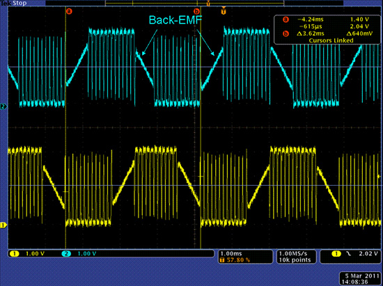
The figure below shows an identical scenario but 4Q Bipolar PWMs are used instead. As the no-load speed approaches zero, the applied motor voltage also approaches zero, and the pulse width approaches fifty percent. Therefore, there is no minimum speed limit imposed by the ADC sampling with Bipolar PWMs. Another advantage is that the back-EMF voltage is visible during both PWM states, not just one.
 TI Figure 3
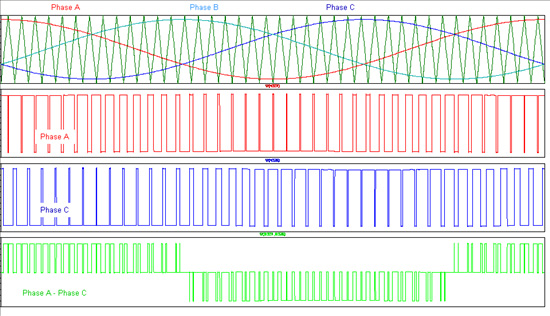
The other multiphase motors in my list are AC motors, and they typically want to be driven by three-phase sinusoidal waveforms. This means that all three phases are driven with PWM signals at the same time, and there aren’t any commutation periods where we turn off one of the phases. The most common modulation technique to use in this case is “center-aligned” PWMs as described in the previous blog on 4Q Unipolar PWMs. A diagram illustrating this process is shown below.
 TI Figure 4
The plots in the top panel show the sinusoidal modulation waveforms superimposed on top of the triangle wave carrier. The next two plot panels show the resulting Phase A and Phase C PWM waveforms. These are the actual voltage waveforms applied to the Phase A and Phase C motor terminals. But remember, the motor is a floating load, so it responds to the difference between the waveforms on its terminals, just as a brush-DC motor does in an H-Bridge. As a result, a unipolar PWM waveform is seen across windings A and C, as shown in the bottom plot. However, curious minds will want to know why the PWM carrier frequency is not exactly doubled, as it was when this same PWM technique was applied to a DC motor. From our last blog, we learned that in order to achieve perfect carrier frequency doubling, two criteria must be met:
1. The two PWM signals must be center-aligned. (Looks like we have met this criterion.)
2. The two PWM signals must be created by modulation waveforms that are equal and opposite in polarity. (Oops. Here’s the problem. Instead of the modulation waveforms being 180 degrees out of phase, the application requires that they must be separated by 120 degrees, which is the case with all three-phase machines.)
Now that we have three continuous PWM signals driving a three-phase inverter, several other interesting possibilities present themselves. For example, can we add common mode components to the modulation waveforms to increase the maximum effective motor voltage compared to sinusoidal waveforms? Can we alter the switching sequences to generate the same effective motor voltage, but reduce switching losses? You can probably tell by the way that I framed each question that the answer is obviously “yes.” But that is the subject of a later blog, when we get to Space Vector Modulation.
In the next and final blog in this series, I want to circle back to the regeneration topic and contrast the different requirements to achieve regen for DC and AC machines. Until then…
Keep those motors spinning! :-)