Index
- BMSBattery S series
- BMSBattery S06S
- S06ST (torque sensor version)
- S06S-BL (Bluetooth version)
- PWM signals
- Phase B current signal
- Throttle
- BMSBattery S06SC
- BMSBattery S12S
- BMSBattery bottle battery controller
- LCD control panel
- Kunteng mobile app
- Bluetooh
- How to open the controller and solder the programming header
- Hardware mods
- Other controllers
- BMSBattery S06P
- Kunteng 18 mosfets motor controller
- Lishui motor controllers
- JinHui motor controllers
- GreenEBikeKit
- Torque speed
- Motor control scheme of S06S controller
- BLDC 6 steps
- PWM schemes
- So, Which PWM Technique is Best? (Part 1)
- So, Which PWM Technique is Best? (Part 2)
- So, Which PWM Technique is Best? (Part 3)
- So, Which PWM Technique is Best? (Part 4)
- So, Which PWM Technique is Best? (Part 5)
- So, Which PWM Technique is Best? (Part 6)
- So, Which PWM Technique is Best? (Part 7)
- PWM control and Dead Time Insertion
- Low inductance motors
- Throttle Control Modes
- Phase angle FOC
- PWM frequency VS motor eRPM
- Sinusoidal Control of BLDCM with Hall Sensors Based
- Self-Learn Hall Sensor Calibration Mode
- STM8S105 Alternatives
- PID algorithm - negative output values
- Regeneration
- FOC
Datasheets and application notes
- STM8S105C6T6
- Endless-sphere.com forum messages
- 2017.04.25 - Initial forum message
- 2017.05.08 - First flash and debug on a dev board
- 2017.05.18 - First code flashing and running
- 2017.05.20 - more new information
- 2017.08.23 - SxxP versus SxxS versus LSW-675
- 2017.09.01 - Trying to figure out an algorithm to automatically adjust ui8_position_correction_value
- 2017.09.02 - How to do FOC on the BMSBattery S06S/Kunteng STM8 motor controllers
- 2017.09.03 - more ideas about zero crossing for FOC
- 2017.09.05 - measuring IQ current and manually adjusting position_correction_value
- 2017.09.15 - our OpenSource firmware efficiency compared to Lishui 12 FET FOC
- 2017.09.19 - measuring motor current
- 2017.10.23 - FOC and no FOC comparison
- 2018.01.10 - How to measure FOC_READ_ID_CURRENT_ANGLE_ADJUST
- 2018.02.20 - Reading motor phase current from the DC link current (shunt)
So, Which PWM Technique is Best? (Part 5)
https://e2e.ti.com/blogs_/b/motordrivecontrol/archive/2012/04/09/so-which-pwm-technique-is-best-part-5So, Which PWM Technique is Best? (part 5)
Dave Wilson, Motion Products Evangelist, Texas Instruments
So, which PWM technique is best for your motor control application? By now you have probably surmised that there is no “one” PWM technique that is the best for all applications. But the technique we are going to discuss today comes pretty close. It's called the Unipolar 4-Quadrant PWM Technique (Form II), which is represented below:
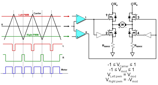
As with the Bipolar PWM technique that I discussed in my last blog, there is no forward/reverse signal. Directional information is encoded within the PWM input levels, which can transition between +1 and -1. Analog comparators are used to compare the input voltage levels against a triangle carrier signal to generate the “L” and “R” PWM signals. In a microcontroller which uses a digital PWM peripheral, the comparison is done digitally between the output of a counter that counts up and down, and a digital word which represents the desired pulse width.
Since each half of the H-Bridge is driven in a complementary fashion, we must include dead-time between the top and bottom PWM signals. Assuming dead-time is supplied internally by the PWM module, this technique requires four PWM pins on your processor! Despite the fact that this technique has an insatiable appetite for PWM signals, it has all the advantages of the previous unipolar topologies, PLUS a unique advantage which can justify its selection in most cases; …it DOUBLES the PWM frequency seen by the motor! We could go through a harmonic decomposition of the waveforms to show this effect mathematically, but it is much easier to understand this effect by simply studying the waveforms above. Assuming that the “L” waveform appears on the left half of the H-bridge, and the “R” waveform appears on the right half of the H-bridge, then the motor will see the difference between these two waveforms. If you subtract the “R” waveform from the “L” waveform, you get the blue waveform, which clearly has twice the PWM frequency as the red or green waveforms. This is usually a desirable feature since the L/R time constant of the motor will be twice as effective at filtering out the carrier harmonics. However, the transistors will still switch at the lower carrier frequency, which is also good for the switching losses in the H-Bridge. This is one of those rare moments in engineering where you can have your cake, and eat it too! :-) To see an animation of this PWM technique operating in Quadrant 1, click on the hyperlink here. A .gif of this technique operating in Quadrant 4 can be seen by clicking on the link here.
In order to achieve the PWM frequency doubling effect, there are two requirements that must be in place:
1. The two PWM signals for each side of the H-Bridge must be center-aligned. Notice the “L” and the “R” signals in the diagram above. The middles of the high-side pulses between the two signals are aligned, as indicated by the dashed vertical lines. Similarly, the middles of the low-side pulses are also aligned. This condition is easily created by selecting the correct operating mode of the PWM module on most motor control processors.
2. The Left and Right PWM threshold values MUST always be equal and opposite in polarity. For example, if the “Left PWM” signal is a sinusoidal waveform, then the “Right PWM” signal must be the same sinewave shifted by 180 degrees. This distinction will become important when we extend this technique to three-phase systems.
With bipolar PWMs discussed in the previous blog, there were no recirculating currents within the H-Bridge, and the motor current always flowed through the shunt resistor. But today’s technique (as with all unipolar PWM techniques) has blackout intervals during portions of the PWM cycle when a single shunt resistor is used, due to recirculating currents within the H-Bridge. Also, if we use a shunt signal amplifier with finite bandwidth and slew-rate specs, we must place limits on the allowable extents of the PWM duty cycle to prevent current pulses on the resistor that are too narrow to be processed by the amplifier. However, if we use TWO resistors as shown above, there will always be an opportunity to read the motor current on at least one of the resistors within the PWM cycle regardless of the duty cycle value. In fact, we now have visibility to the motor current even when it is recirculating within the bottom half of the H-Bridge! The disadvantages of this approach however are rather obvious, and include having twice as many components for current sensing, and twice the power loss dissipated by the shunt resistors.
A VisSim simulation which compares this PWM technique to the classic Bipolar PWM technique can be found here. Again, if you don’t have VisSim installed on your computer, you can download and install a free VisSim file viewer at the link here. Go ahead and open the file and click the green RUN arrow. Change the PWM duty-cycle slider and compare the current ripple for the unipolar technique to that of the bipolar technique, especially at lower duty cycle values. The lower current ripple results in less heating in the motor, and represents the main advantage of this technique.
Up to now, we have only discussed the application of PWMs to DC motors. But what about AC motors? In the next blog in this series, we will extend this unipolar PWM technique to multi-phase applications, and conclude with a further investigation of regeneration and plugging. In the meantime…
Keep those motors spinning! :-)