Index
- BMSBattery S series
- BMSBattery S06S
- S06ST (torque sensor version)
- S06S-BL (Bluetooth version)
- PWM signals
- Phase B current signal
- Throttle
- BMSBattery S06SC
- BMSBattery S12S
- BMSBattery bottle battery controller
- LCD control panel
- Kunteng mobile app
- Bluetooh
- How to open the controller and solder the programming header
- Hardware mods
- Other controllers
- BMSBattery S06P
- Kunteng 18 mosfets motor controller
- Lishui motor controllers
- JinHui motor controllers
- GreenEBikeKit
- Torque speed
- Motor control scheme of S06S controller
- BLDC 6 steps
- PWM schemes
- So, Which PWM Technique is Best? (Part 1)
- So, Which PWM Technique is Best? (Part 2)
- So, Which PWM Technique is Best? (Part 3)
- So, Which PWM Technique is Best? (Part 4)
- So, Which PWM Technique is Best? (Part 5)
- So, Which PWM Technique is Best? (Part 6)
- So, Which PWM Technique is Best? (Part 7)
- PWM control and Dead Time Insertion
- Low inductance motors
- Throttle Control Modes
- Phase angle FOC
- PWM frequency VS motor eRPM
- Sinusoidal Control of BLDCM with Hall Sensors Based
- Self-Learn Hall Sensor Calibration Mode
- STM8S105 Alternatives
- PID algorithm - negative output values
- Regeneration
- FOC
Datasheets and application notes
- STM8S105C6T6
- Endless-sphere.com forum messages
- 2017.04.25 - Initial forum message
- 2017.05.08 - First flash and debug on a dev board
- 2017.05.18 - First code flashing and running
- 2017.05.20 - more new information
- 2017.08.23 - SxxP versus SxxS versus LSW-675
- 2017.09.01 - Trying to figure out an algorithm to automatically adjust ui8_position_correction_value
- 2017.09.02 - How to do FOC on the BMSBattery S06S/Kunteng STM8 motor controllers
- 2017.09.03 - more ideas about zero crossing for FOC
- 2017.09.05 - measuring IQ current and manually adjusting position_correction_value
- 2017.09.15 - our OpenSource firmware efficiency compared to Lishui 12 FET FOC
- 2017.09.19 - measuring motor current
- 2017.10.23 - FOC and no FOC comparison
- 2018.01.10 - How to measure FOC_READ_ID_CURRENT_ANGLE_ADJUST
- 2018.02.20 - Reading motor phase current from the DC link current (shunt)
2018.01.10 - How to measure FOC_READ_ID_CURRENT_ANGLE_ADJUST
There is a parameter on the firmware that can be adjusted to optimize the motor controller efficiency to the max possible, meaning the used battery energy will be the lowest possible to run the motor.
One way to find the best value for that parameter (FOC_READ_ID_CURRENT_ANGLE_ADJUST) is by running the motor with a constant load and adjust the parameter value up to get the lowest battery energy used.
Since it is difficult to run the motor with a constant load, a new way to calculate the ideal value is proposed.
Calculate FOC_READ_ID_CURRENT_ANGLE_ADJUST by looking at hall sensor and BEMF signals
Considering that pushing by hand the motor will generate a BEMF voltage signal at his phases terminals, we can measure this signals and compare with hall sensor signals: the time difference between zero cross of each signals will let us calculate the FOC_READ_ID_CURRENT_ANGLE_ADJUST.
Example of voltage signal readings on oscilloscope (motor BMSBattery Q85 24V 328 RPM).
Blue line is hall sensor signal (B) (hall sensor green wire) and yellow line is phase B signal (motor phase B green wire):
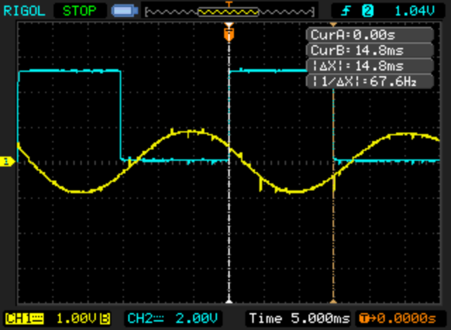
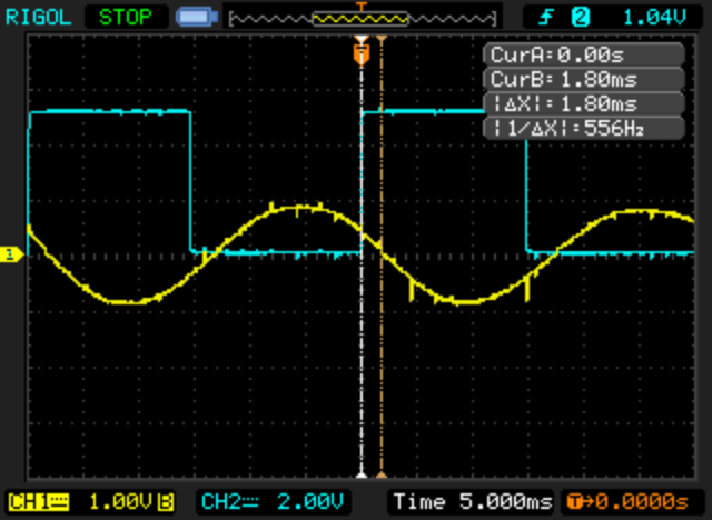
As we can see, there is a small offset of 1.8ms between the signals.
Let's calculate FOC_READ_ID_CURRENT_ANGLE_ADJUST based on that offset:
• signal period is: 14.8 * 2 = 29,6ms (as seen on first picture).
• our firmware divides the signal period in 256 steps, so the offset of 1.8ms is: (1.8 * 256)/ 29,6 ~= 16 steps
• FOC_READ_ID_CURRENT_ANGLE_ADJUST base value is 127 steps and so we need to add 16, and the final value will be: 143.
Another example of voltage signal readings on oscilloscope (motor BMSBattery Q11 48V 370RPM).
Blue line is hall sensor signal (B) (hall sensor green wire) and yellow line is phase B signal (motor phase B green wire):

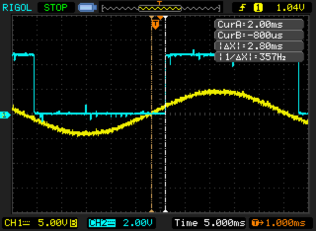
As we can see, there is a small offset of 2.8ms between the signals (on this motor, the phase voltage is behind the hall sensor signal).
Let's calculate FOC_READ_ID_CURRENT_ANGLE_ADJUST based on that offset:
• signal period is: 27 * 2 = 54ms
• our firmware divides the signal period in 256 steps, so the offset of 1.8ms is: (2.8 * 256)/ 54 ~= 13 steps
• FOC_READ_ID_CURRENT_ANGLE_ADJUST base value is 127 steps and so we need to subtract 13 (subtract because phase voltage is behind the hall sensor signal), and the final value will be: 114.
How to read the signals using an oscilloscope
• wire 3 resistors, of 47k ohms each one, in a star to have a common connection point between them:
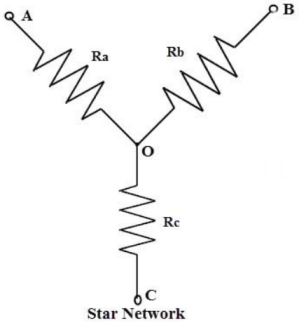
• connect each motor phase wires to points A, B and C of the star
• connect ground wire of oscilloscope to point O (middle point of star)
• connect oscilloscope channel A probe to point B (motor phase B green wire)
Next, we need to connect oscilloscope channel B probe to hall sensor green wire. But the hall sensors need to be powered, so connect them to the motor controller and power it up. Connect the motor controller ground to point O (middle point of start).
Now you can rotate the motor by hand and see on the oscilloscope the generated voltage waveforms.
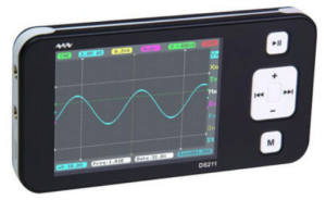
NOTE: If you need an oscilloscope, you can buy a cheap 70€ portable oscilloscope that should be enough for this task (find on Ebay searching for “DSO oscilloscope”:
• video: https://www.youtube.com/watch?v=RCEHAOyxHRY