Index
- BMSBattery S series
- BMSBattery S06S
- S06ST (torque sensor version)
- S06S-BL (Bluetooth version)
- PWM signals
- Phase B current signal
- Throttle
- BMSBattery S06SC
- BMSBattery S12S
- BMSBattery bottle battery controller
- LCD control panel
- Kunteng mobile app
- Bluetooh
- How to open the controller and solder the programming header
- Hardware mods
- Other controllers
- BMSBattery S06P
- Kunteng 18 mosfets motor controller
- Lishui motor controllers
- JinHui motor controllers
- GreenEBikeKit
- Torque speed
- Motor control scheme of S06S controller
- BLDC 6 steps
- PWM schemes
- So, Which PWM Technique is Best? (Part 1)
- So, Which PWM Technique is Best? (Part 2)
- So, Which PWM Technique is Best? (Part 3)
- So, Which PWM Technique is Best? (Part 4)
- So, Which PWM Technique is Best? (Part 5)
- So, Which PWM Technique is Best? (Part 6)
- So, Which PWM Technique is Best? (Part 7)
- PWM control and Dead Time Insertion
- Low inductance motors
- Throttle Control Modes
- Phase angle FOC
- PWM frequency VS motor eRPM
- Sinusoidal Control of BLDCM with Hall Sensors Based
- Self-Learn Hall Sensor Calibration Mode
- STM8S105 Alternatives
- PID algorithm - negative output values
- Regeneration
- FOC
Datasheets and application notes
- STM8S105C6T6
- Endless-sphere.com forum messages
- 2017.04.25 - Initial forum message
- 2017.05.08 - First flash and debug on a dev board
- 2017.05.18 - First code flashing and running
- 2017.05.20 - more new information
- 2017.08.23 - SxxP versus SxxS versus LSW-675
- 2017.09.01 - Trying to figure out an algorithm to automatically adjust ui8_position_correction_value
- 2017.09.02 - How to do FOC on the BMSBattery S06S/Kunteng STM8 motor controllers
- 2017.09.03 - more ideas about zero crossing for FOC
- 2017.09.05 - measuring IQ current and manually adjusting position_correction_value
- 2017.09.15 - our OpenSource firmware efficiency compared to Lishui 12 FET FOC
- 2017.09.19 - measuring motor current
- 2017.10.23 - FOC and no FOC comparison
- 2018.01.10 - How to measure FOC_READ_ID_CURRENT_ANGLE_ADJUST
- 2018.02.20 - Reading motor phase current from the DC link current (shunt)
So, Which PWM Technique is Best? (Part 1)
https://e2e.ti.com/blogs_/b/motordrivecontrol/archive/2012/03/19/so-which-pwm-technique-is-best-part-1So, Which PWM Technique is Best? (Part 1)
Dave Wilson, Motion Products Evangelist, Texas Instruments
So, which PWM technique is best for your motor control application? In case you haven’t guessed, this is somewhat of a trick question. It’s kind of like asking “which ice-cream flavor is the best”, since everybody knows that the answer is obviously “chocolate chip.” There aren’t quite as many flavors of PWM as there are ice cream, but there are perhaps more of them than you realize. And which one works best for your application obviously depends on your application. So let’s spend some time over the next few blogs looking at different PWM topologies, along with their advantages and disadvantages, in an effort to pick the one that’s right for you.
For those of you who are more experienced motor control engineers, please indulge me for a moment while I set the stage for this topic. It is not possible to have a meaningful discussion about different PWM techniques without first understanding how energy transfer occurs in a motor. When studying energy transfer, we typically refer to a two dimensional speed-torque diagram as shown below, where speed is the x-axis, and torque is the y-axis.
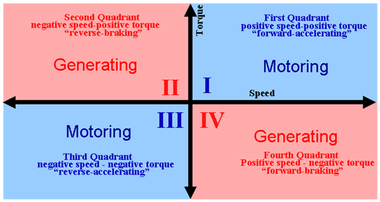
If you multiply speed times torque, you get power. So area in the above diagram corresponds to power. The blue areas are regions where the motor power is positive (i.e., the motor is converting electrical power into mechanical power). But the red areas on the graph indicate regions where the motor power is negative (i.e., the motor is converting mechanical power into electrical power). This is where you can run into problems if you are not careful. If the motor is generating electrical power, you need to have some place for that power to go. If your application is an electric vehicle coasting down a hill, the generated electrical energy can be put to good use by charging the batteries. But if you have an electric drive which needs to stop its load abruptly, the resulting generator action can destroy the drive if there is no place to put the energy.
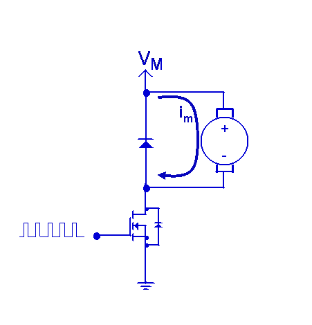
Some PWM topologies will inherently prevent regeneration of energy back into your electrical supply. In fact, some will only allow the motor to spin in one direction and generate torque in that same direction. These drives as you might expect are called single-quadrant drives and operate either in quadrant 1 or quadrant 3. A typical example of such a drive is shown below, where a PWM signal is applied to a single transistor. These types of motor drives are common in applications where cost is critical, such as toys, electric baby swings, and so on. The motor can only spin in one direction and generate torque in that same direction. If you try to decelerate the motor (i.e., generate negative braking torque) by lowering the duty cycle, the motor will simply coast down slowly. This is because there is no way with this configuration to create negative current in the motor. All of the kinetic energy in the spinning load is eventually dissipated as heat in the load’s friction, and none of it is converted back into electricity.
However, if you want the motor to go forward AND backward, you need to provide a way to drive the motor current in the negative direction. You could achieve this with a separate negative power supply, but this is usually cost prohibitive. A more common approach is to put the motor in an “H-Bridge” as shown below. Now you have four transistors, each capable of being switched ON and OFF independently. This allows for some rather interesting possibilities since we now have a configuration capable of operating in all four quadrants. How you switch the transistors with respect to each other will determine which power quadrants the motor will operate in.
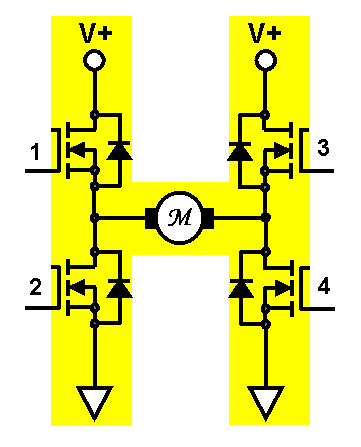
In our next blog, we will investigate how to use the above H-Bridge configuration to create a unipolar two-quadrant drive.