Index
- BMSBattery S series
- BMSBattery S06S
- S06ST (torque sensor version)
- S06S-BL (Bluetooth version)
- PWM signals
- Phase B current signal
- Throttle
- BMSBattery S06SC
- BMSBattery S12S
- BMSBattery bottle battery controller
- LCD control panel
- Kunteng mobile app
- Bluetooh
- How to open the controller and solder the programming header
- Hardware mods
- Other controllers
- BMSBattery S06P
- Kunteng 18 mosfets motor controller
- Lishui motor controllers
- JinHui motor controllers
- GreenEBikeKit
- Torque speed
- Motor control scheme of S06S controller
- BLDC 6 steps
- PWM schemes
- So, Which PWM Technique is Best? (Part 1)
- So, Which PWM Technique is Best? (Part 2)
- So, Which PWM Technique is Best? (Part 3)
- So, Which PWM Technique is Best? (Part 4)
- So, Which PWM Technique is Best? (Part 5)
- So, Which PWM Technique is Best? (Part 6)
- So, Which PWM Technique is Best? (Part 7)
- PWM control and Dead Time Insertion
- Low inductance motors
- Throttle Control Modes
- Phase angle FOC
- PWM frequency VS motor eRPM
- Sinusoidal Control of BLDCM with Hall Sensors Based
- Self-Learn Hall Sensor Calibration Mode
- STM8S105 Alternatives
- PID algorithm - negative output values
- Regeneration
- FOC
Datasheets and application notes
- STM8S105C6T6
- Endless-sphere.com forum messages
- 2017.04.25 - Initial forum message
- 2017.05.08 - First flash and debug on a dev board
- 2017.05.18 - First code flashing and running
- 2017.05.20 - more new information
- 2017.08.23 - SxxP versus SxxS versus LSW-675
- 2017.09.01 - Trying to figure out an algorithm to automatically adjust ui8_position_correction_value
- 2017.09.02 - How to do FOC on the BMSBattery S06S/Kunteng STM8 motor controllers
- 2017.09.03 - more ideas about zero crossing for FOC
- 2017.09.05 - measuring IQ current and manually adjusting position_correction_value
- 2017.09.15 - our OpenSource firmware efficiency compared to Lishui 12 FET FOC
- 2017.09.19 - measuring motor current
- 2017.10.23 - FOC and no FOC comparison
- 2018.01.10 - How to measure FOC_READ_ID_CURRENT_ANGLE_ADJUST
- 2018.02.20 - Reading motor phase current from the DC link current (shunt)
Sensorless Pneu Scooter - part 1
Saturday, December 17, 2011
Sensorless Pneu Scooter: Part 1
After just about one month, my voluntary moratorium on Pneu Scooter riding is officially over. Yes, that means it is now Sensorless Pneu Scooter. Even though I was distracted by flying things for a short period of time, I have made steady progress on working out the software kinks to get my first attempt at a sensorless field-oriented control strategy up and running. This is a two-week update, so I think I'll have to split it into two parts. The first part here explains most of the code tweaking I did. The second part, to come shortly, is when the sensorless control finally begins to work the way it should. How the two parts are related to each other, I don't exactly know.
Part 1: Where I make my code much fancier.
In the last update, I had been able to get Pneu Scooter running for a short indoor test drive on sensorless control. While it worked at low speed and low load, it was glitchy at anything above 20A and seemed to completely fail at 800rpm. These may have been related or unrelated problems, and I never got far enough into troubleshooting it to find out. Instead, while test-driving, one of the glitches took out the power stage, killing the FET, at least two gate drivers, and leaving a small crater where my DC current sensor used to be:
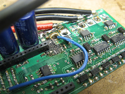
In a previous FET failure, the trace leading into the DC bus had blown, so I reinforced it with some copper braid. This moved the weakest link to the current sensor, I guess. It's worth noting that there is a 40A slow fuse in the system but it seems never to actually do anything during failures. Maybe time to go back to the magnetically-tripped circuit breaker switch. In any case, this board is toast. Even after I repair the power stage, it will only work with the DC current sensor bypassed completely. Possible motivation to design 3ph v4.0.
I switched to my back-up 3ph v3.1 controller and took some time to implement a few software improvements, including fast over-current shutdown designed to (possibly) save the FETs if (when) the sensorless control commutation glitches. I also implemented a better ADC sampling strategy to try to clean up the current measurements as much as possible. The goal was to sample phase currents at a time where no power switching is happening, since the switching transients can couple noise onto the current sensor signals.
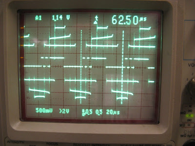
First, the three PWM timers are synchronized (no easy task) and set to center-aligned mode, producing nested and symmetric voltage ouputs. In addition to reducing ripple on the DC bus capacitors, this has the benefit of creating a guaranteed point in time where all three PWMs are off. This is where I wanted to trigger the ADC to sample phase current. The STM32F103 has all sorts of interesting timer and ADC setup nuances that I discovered. After several days of messing around with timer and ADC configuration registers, I got to this:
| click me |
|---|
| Scopemas Tree. |
I had to overlap the three voltage outputs to get all the traces to fit on the scope. Here, they are running with duty cycles of 25%, 50%, and 75%, just to illustrate what center-timed PWM looks like. Timer 1 is the master and the other two are synchronized to it. I set up an unused Timer 1 compare output as the trigger for the ADC, and I configured the dual ADC so I can convert two measurements simultaneously. I group and order the measurements as follows:1. Phase A Current & Phase C Current
2. DC Current & DC Voltage
3. Throttle & Nothing
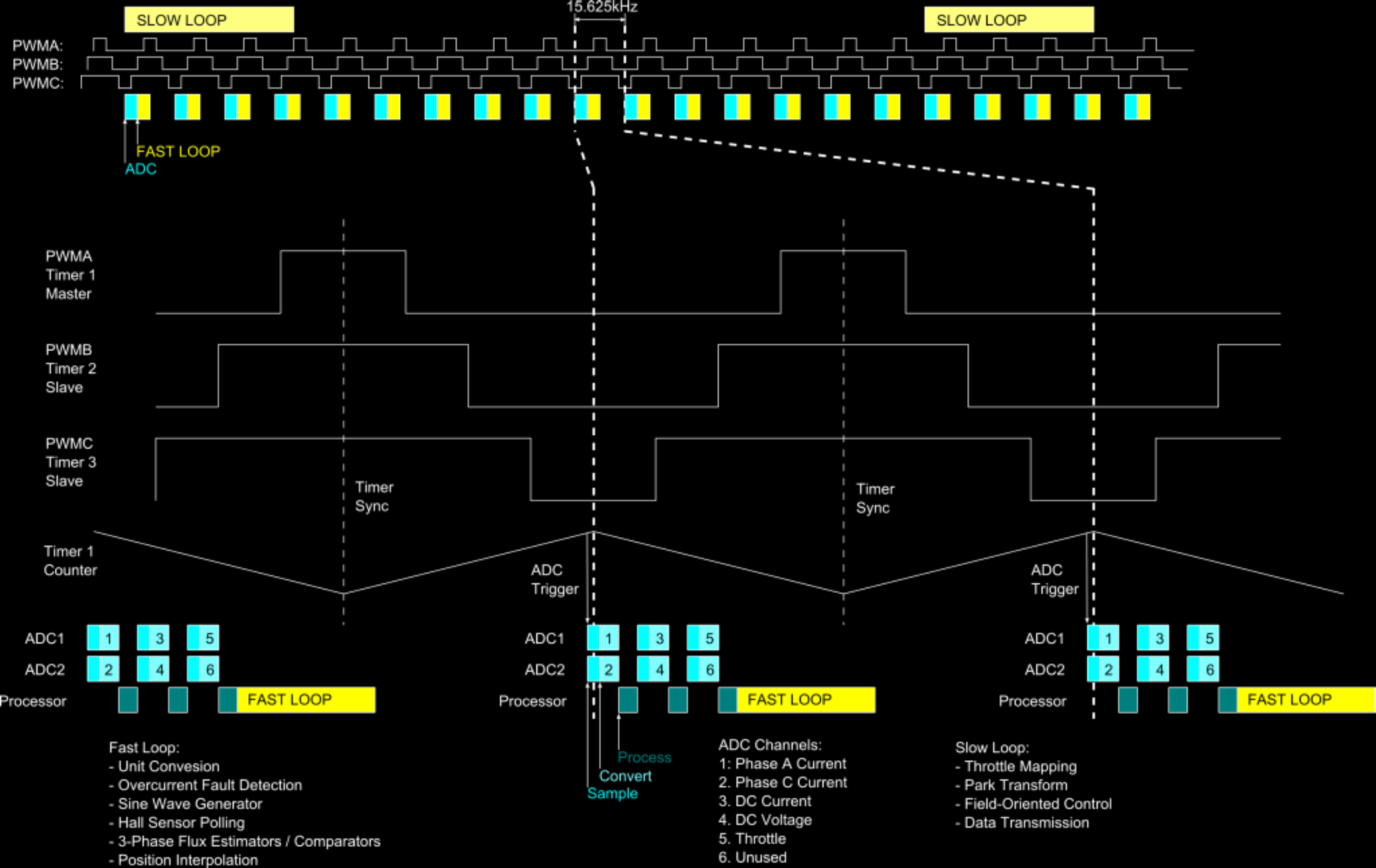
The phase current measurements are most important, so they go first, triggered just before the center of the "off" portion of all three PWMs. The other measurements are more heavily filtered in hardware and software, so I don't care about protecting them from the switching transients. With my ADC configuration, it takes about 1.7μs to sample the two phase current analog signals. So, I set the ADC trigger to occur about 0.85μs before dead-center and expect it to finish 0.85μs after dead-center. After that, there is about another 2μs of conversion time, when the ADC translates the sampled voltage into a digital value. Then, an interrupt is triggered which stores the result in a variable. Zooming in on the center of the PWM, the timing of the first two sample-and-converts is something like this:
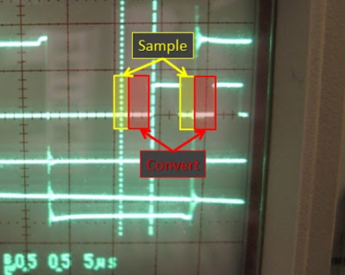
This scope plot also shows the motivation for sampling the phase currents away from the transitions. The tiny bits of ringing at each switching event show up everywhere: on other voltage outputs and on the digital line being used to illustrate processor timing. So, by leaving a window where all three PWMs are off and sampling the phase currents exactly in that window, the noise is hopefully reduced. The width of this "all-off" window has to be just a bit wider than the ADC sample time of 1.7μs, so perhaps 2μs. That limits the maximum duty cycle at 15.625kHz to 2μs/64μs, about 96.8%. Since the gate drivers are bootstrapped anyway and need some off-time to work at all, this seems like a reasonable limit.
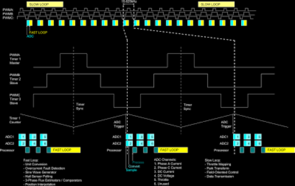
After the three sets of ADC conversions, the fast loop is triggered and runs the sensorless field-oriented control routine using the freshly-converted current measurements. I also added some fast over-current shutdown code to kill the gate drive if any of the phase currents or the DC current exceed a maximum limit, positive or negative. Hopefully the combination of cleaner current measurments and shutdown within 64μs of an overcurrent fault will have some chance of saving the FETs if there is a controller glitch.
In case the last 1,000 words weren't very clear, here's a graphic showing the controller timing in its entirety:
| click me |
|---|
| (Click to enlarge.) |
There are still some minor tweaks I want to make to the code. One way to save a ton of time is to use the Direct Memory Access (DMA) peripheral to automatically store ADC results in memory. Theoretically, this would cut the entire ADC block down to about 10μs. I'm also still running at only 32MHz. I don't need it yet, but the processor is capable of 72MHz in case I want to add more fanciness to my fast loop.
But for now, this setup seems fine. After loading the new version of the controller, Sensorless Pneu Scooter magically started working the way it should. I didn't think I had changed anything fundamental, but the performance is much better than it was before, almost indistinguishable from the previously-sensored Pneu Scooter. I've been riding it around for a few days now with no problems.
In Part 2, I'll get to the sensorless scheme itself and the data I've collected during my few days of test driving...
Posted by Shane Colton at 8:53 AM Labels: field-oriented control, FOC, pneu, pneu scooter, sensorless