Tutorial for data logging with USB-UArt adapter or Bluetooth
module HC-05
This tutorial describes how to wire the controller with the UART module
and how to use the software on PC/Laptop or Smartphone.1. Wiring
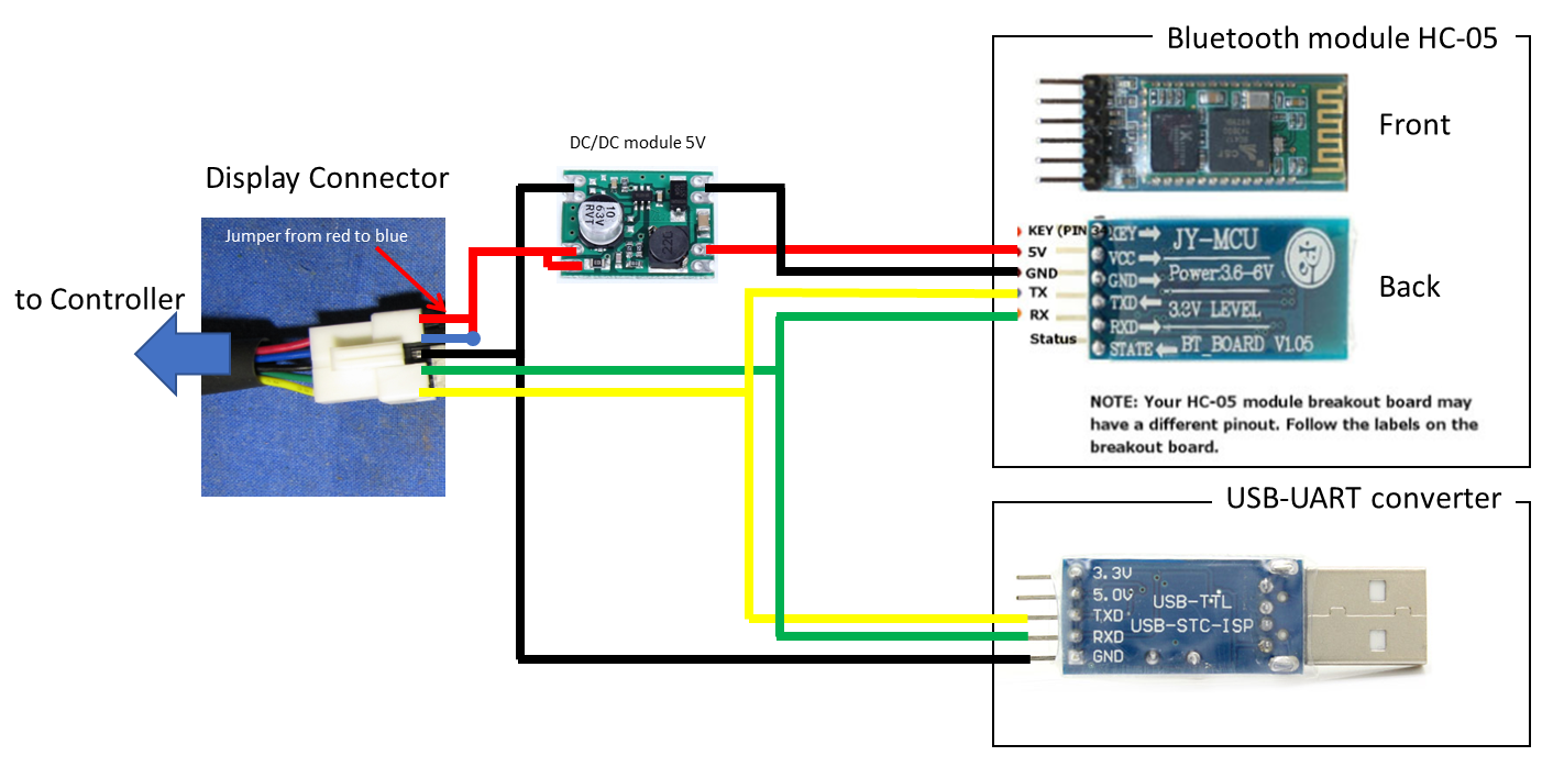
- connect red to blue at the display connector of the controller with a jumper to switch on the system
- for Bluetooth module: power supply via 5V DC/DC module. Connect VCC of the BT-module with the V+ out pad of the DC/DC module.
Never connect VCC directly to the red wire of the display connector, this will destroy the module!
- for Bluetooth and USB-UART module: connect black wire from the display connector to GND of the module, the yellow one to Rx and the green one to Tx.
For the use of the BluOsec--app the USB-UART-module is not needed, just ignore it.
------------------------------------------
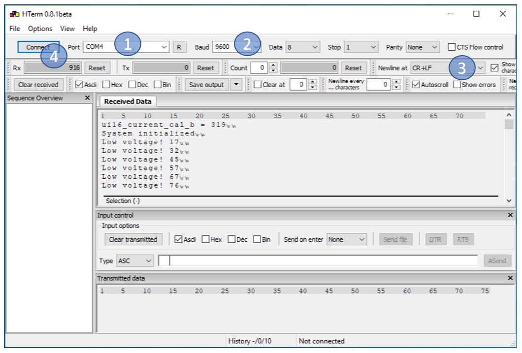
2. Using USB-UART-Converter with HTerm on a windows system.
- Download and unpack HTerm
- Plug in the USB-UART converter. It should install automatically. An virtual com-port is created, you can check the port number in the device-manager (right-click on windows-start-symbol --> device manager --> Ports (COM & LTP))
- Start HTerm by doubleclick on HTerm.exe (at the location, you have unpacked it)
1. select the COM port of the converter
2. set the Baud-rate to 9600
3. set the Newline command to CR+LF
4. press the Connect button.
If you switch on the controller now, you should see the data sent from the controller in the Received Data window.
------------------------------------------
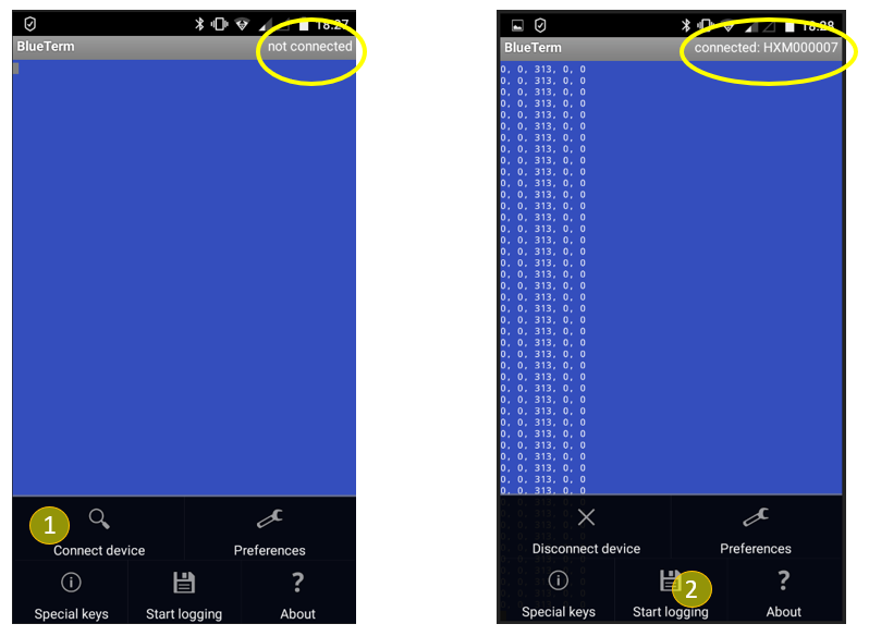
2. Using the HC-05 Bluetooth Module with the BlueTerm-App on an android smartphone.
- install BlueTerm from the playstore
- pair your smartphone with the bluetooth module via the bluetooth settings menu of your smartphone (module has to be powered of course) The module is shown as HX... in the list of available devices. Password is 1234 normally.
- start the BlueTerm app
- open the settings dialog by pressing the options/menu button of the smartphone. (often long press to one of the home/return... buttons, this varies from smartphone to smartphone)
- press Connect device and choose the HX... Now the module will be connected to the Blueterm app. This takes a little time and sometimes aborts. Then just try again. The connection status is shown in the upper right corner of the screen.
- the data sent from the controller will be shown on the screen if the module is connected
- to log the data for later analyzing open the menu again an press the start logging button. To stop again, open menu, press stopp logging. The log file can be found directly in the main folder of your android data section.
------------------------------------------
3. Setting the parameters sent from the controller.
you have to edit this line in the main.c to set the parameters you want to get printed. Use following format tags:
%u unsigned 8 and 16 bit numbers
%lu unsigned 32 bit numbers
%d signed 8 and 16 bit numbers
\r\n CR+LF
#ifdef DIAGNOSTICS
printf("%u, %lu, %u, %u, %u, %u\r\n", ui16_setpoint, uint32_current_target, ui16_BatteryCurrent, ui16_PAS, ui16_sum_torque, (uint16_t) ui32_SPEED_km_h);
#endif
List of available parameters (not complete):
| ui16_setpoint | duty cycle (0...255) |
| uint32_current_target | target for battery current, calculation see chapter 4, input for PI-controller |
| ui16_BatteryCurrent | ADC-reading of recent battery current (10bit resolution), calculation see chapter 4, input for PI-controller |
| ui16_PAS | number of fast loop timer interrupts between two PAS interrupts |
| ui16_sum_torque | ADC-Reading of throttle input pin in Throttle and Torque-Simulation mode, sum of ADC Reading per PAS impulse for one pedal revolution (8bit ADC resolution) |
| ui32_SPEED_km_h | speed from external sensor x 1000 |
| ui8_position_correction_value | advance angle from simplyfied FOC |
| ui16_motor_speed_erps | electric revolutions per second |
| ui16_adc_read_battery_voltage() | ADC-reading of battery voltage (10bit resolution) |
| ui8_regen_throttle | ADC-reading from pad X4 (8bit resolution) |
| cheatstate | recent status of cheat procedure, normally zero, 5 if offroad mode is activated |
| ui8_control_state | 0 booting 1 linear regen 2 undervoltage 3 brake/digital regen 4 erps limiting 5 PAS timeout 6 power in torquesensor mode 7 power in throttle mode 8 phase current limiting 9 power in torquesimulation mode 10 throttle override 11 speedlimit cut internal sensor 12 speedlimit ramp down internal sensor 13 speedlimit cut external sensor 14 speedlimit ramp down external sensor |