Preparing the Hardware
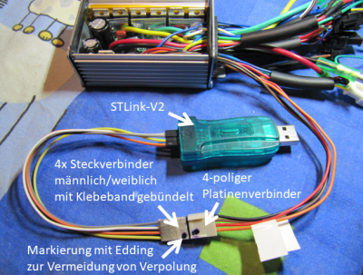
Describes how to solder the board connector and connect it to the
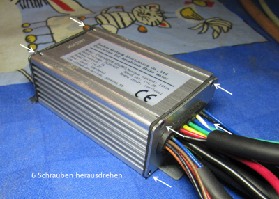
STLink-V2.1. Unscrew the four screws on the end face with the cable outlet and the two top screws on the opposite side. Carefully lift off the cover with the inscription.
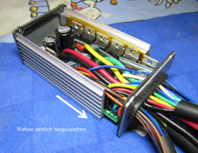
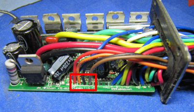
2. Unscrew the three screws (fastening the FETs) on the narrow longitudinal side.
3. remove the controller board carefully with the cable cover
4. Use a pointed object to carefully insert an additional hole into the rubber sleeve of the cable outlet. Carefully ensure that no other cable is damaged.
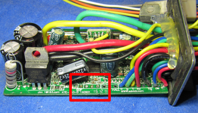
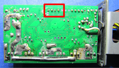
5. Thread the cable ends of the PCB connector from the outside through the pierced hole.
6. insert the cable ends into the soldering eyes of the board and solder them in. Make sure that the cable ends do not protrude further out of the PCB than the existing cables, if necessary pinch off excess length with string cutter. Write down which cable colour was soldered to which connection! It is recommended to solder red on 5V and black on GND, as long as these colours are available on the PCB connector.
7. Carefully push the PCB back into the housing, making sure that the insulation strips are in the right place again.
8. Screw the housing together again. Start with the three fixing screws of the FETs, on which you can despair.....; -)
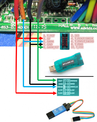
9. Make the connection between the controller and the STLink-V2 using the jumpers.
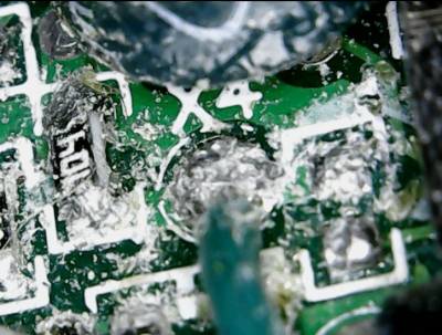
10. For some extra functions, you can solder a wire to terminal "X4" and rout it outwards.