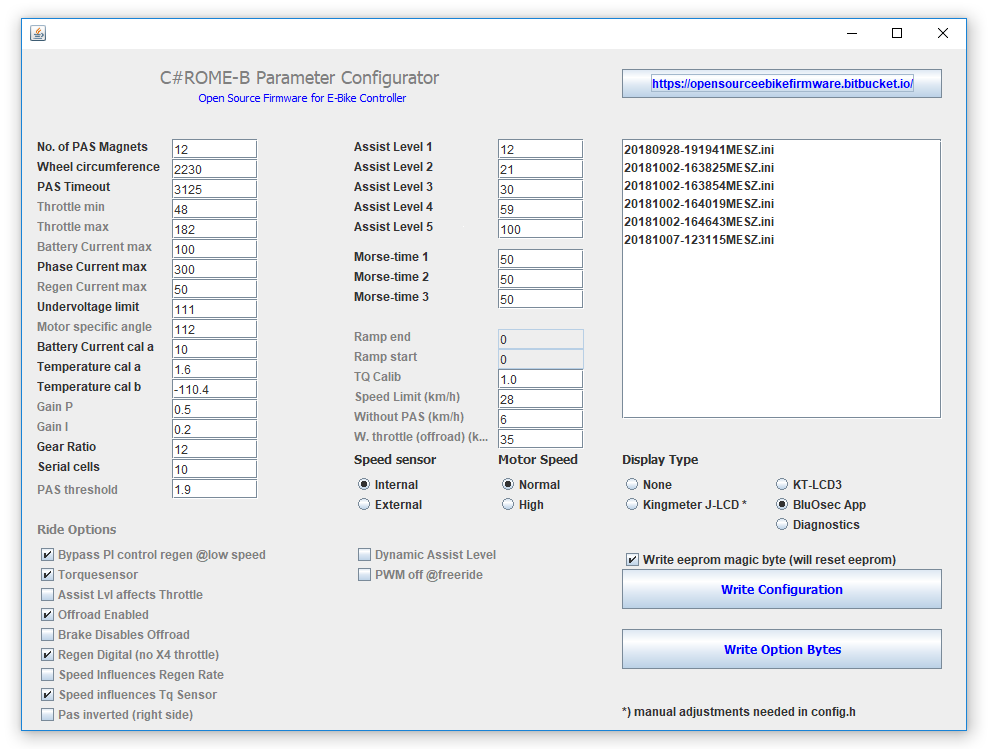
Description of the User Interface
For easy handling of the firmware there is a graphical tool based on
Java.
The tool is started by double-clicking on "OSEC Parameter Configurator.
jar" in the project directory.
First you have to disable the write protection of a new controller by clicking on the button "Write Option Bytes" once. Attention! If this function is selected, the original Kunteng firmware will be irretrievably deleted! Please make sure to find out the correct phase and Hall sensor assignment on the complete system with the original firmware before deleting. This makes sure, that the controller and the motor work together in principle. Still it can be necessary to swap the wires after flashing the firmware to a different combination. If the motor doesn't start properly with the custom firmware (turns not or only very slowly with noise and high current) try to find the right combination by trial and error. Also test the other peripheral devices such as throttle, PAS and brake lever for correct function on the entire system beforehand!
All relevant parameters can be set in the Tool, the parameters in grey letters can be changed by the BluOsec-App afterwards also.
The parameter description is not completely up to date, check the readme.md file at github, if there are newer informations.
The meaning of the individual parameters:
Number of PAS magnets:
Number of magnets in the PAS disk. Required for correct calculation of
the cadence
Wheel circumference: Wheel
circumference in millimetres, is required to calculate the speed. The
setting in the display is ignored.
PAS Timeout:
Time to stop motor after stopping pedaling. Value in 64µs for Motor
Speed = Normal, 48µs for Motor Speed = High. Calculation
example: 3125*0,000064s = 0,2s
Speed Limit (km/h):
Self-explanatory
Assist factor:
Factor for calculating the torque sensor mode support. Calibration
factors of the measurement chain are summarized here. Greater value:
More support with equal human performance. The value is internally
offset with the percentage defined in the Assist level.
Throttle min:
Voltage at closed throttle or torque signal. Required for
adapting the throttle signal to full 8bit resolution of the PWM value.
Conversion: 0V corresponds to 0, 5V corresponds to 255 (8bit resolution
of the AD converter)
Throttle max:
Voltage at full throttle or full deflection of the
torque signal, explanation analogous to Throttle min
Battery Current max:
maximum battery current in deziAmps. A value of 150 means 15A.
Phase Current
max:
maximum phase current. Calculation like Battery Current max. The phase
current is derived from the formula phase current = battery current /
duty cycle internally.
Regen Current max:
maximum recuperation current. Calculation analogous to Battery Current
Undervoltage limit:
Undervoltage cutoff value. Calculation: Value in volts times 3.7.
example: 34.3V * 3.7 = 127
Motor specific angle:
with this value the timing of the motor control can be changed. As a
result, manufacturing inaccuracies of the Hall sensor positions in the
motor can be compensated. Only change if the motor starts badly.
Battery Current cal a: Required for internal calculation of the current from the 10bit ADC
value. Only needs to be changed if the calibration obviously does not
fit with the preset values. For 6FET the default value is 100, for 12 and 18FET the value should be about 50.
Temperature cal a: Factor a in the calibration function temperature in °C = a * ADC value + b. For temperature calculation from external sensor connected to pad X4 and GND. Temperature is shown in the LCD3 but not processed to reduce power if temperature is getting to high actually.
Temperature cal b: Factor b in the calibration function temperature in °C = a * ADC value
+ b. Default values are for a KTY84 sensor.
Gear ratio:
Ratio of electrical revolutions to wheel revolutions. The value is half
the value of P1 for Kunteng displays, since P1 uses the number of
magnets and for Gear Ratio, we need the number of pole pairs. Only
needed if option Speed sensor = Internal.
Assist Level 1:
Support factor level 1 in torque sensor and torque simulation mode.
Calculated as a percentage with the assist factor / maximum battery
current
Assist Level 2 to Assist
Level 5: see Assist Level 1
Morse-time 1:
Is the first time of the morse code in 1/50s. The value 50 means one
second. The cheat works like this: Hold the brake lever for cheat time
1, then release it for the duration of cheat time 2, then pull it
again for cheat time 3, then release it again. For step 1 with a value
of 50, the release of the brake lever is recognized as valid for a
period of 1 to 1.5 seconds after pulling and continues with step 2. If
the lever is released too early or too late, the whole procedure is
reset and you have to start all over again. Currently the user does not
get any feedback on whether the cheat has been activated.
Morse-time 2 and Morse-time 3: see cheat-time 1
Ramp end:
Duration of time between two PAS pulses in 64µs (48µs for Motor speed =
High), which belongs to the
desired limit cadence in torque simulation mode. Value = 60/
((Wish cadence in 1/min)*Number of PAS magnets*64µs). Example
calculation for a
limit cadence of 60/min: 60/ (60*16*0,000064)=977
GAIN P:
Proportional factor of the PI controller. The higher the value is
selected, the higher the risk, that the control starts oszillating.
GAIN I:
Integral factor of the PI controller. The smaller the value, the
smoother the control runs into the setpoint. Both gain values must be
written with a dot as a decimal separator.
Serial cells:
Number of battery cells connected in series. For 36V systems normally
"10", for 24V systems "7", this information is required for
the correct display of the bars in the LCD3-display.
Motor Speed ->
Normal: PWM frequency 15.625 kHZ, sufficient for direct
drive and most hub and mid-engines.
Motor Speed ->
High: PWM frequency 20.833 kHz, for very fast rotating
motors
Display Type ->
None: No
display support. However, parameters (currently
fixed in the code) can be sent to a laptop or to the smartphone via a
Bluetooth module. To change the output parameters, see the tab
"5.Programming new features". Without display, support level 3 is
preset. Connect Rx of the display connector to GND (yellow to black) if
you don't want to sent any data to the controller, even if you use Tx
for diagnostics.
Display Type ->
Kingmeter J-LCD: Support of the Kingmeter J-LCD and the
Lishui Forerider-App. At present, only the normal operating mode works,
the programming mode of the display and the app are not supported.
Display Type ->
KT-LCD3: Support of Kunteng LCD3, only the speed and wheel
size are used. All other settings are currently without function.
Ride Mode ->
Throttle: Operation with throttle handle without PAS
detection, the motor runs even without pedaling
Ride Mode ->
Throttle and PAS: Operation with throttle handle with PAS
detection, motor only runs when pedaling.
Ride Mode ->
Torque Sensor: Motor control proportional to the driver's
performance. Power of the motor = factor * torque at the crank *
cadence It follows from this that there is no support at starting up,
since the cadence is still zero here.
Ride Mode ->
Torque Simulation: Motor current is increased
proportionally to the cadence to the predefined current stage at the
limit cadence defined in Ramp End. If the recent cadence is faster than
the limit
cadence, the current stage is held.
Speed sensor ->
Internal: Speed is calculated from the motor commutation.
No speed is displayed here for motors with freewheel function when the
motor is at standstill.
Speed sensor ->
External: Speed is calculated from external sensor signal.
The speed is always correctly displayed here, even when the motor is at
a standstill and in the case of middrive motors.
PAS direction –> Right/Left: Switch the direction, if motor runs only while pedaling in reverse
Diagnostics:
If this option is activated, the display protocol is not sent via UART,
but some selected internal variables. These five values are sent as
default:
PAS threshold: Threshold for direction detection from the PAS signal. The value should be the arithmetic mean of the reciprocal of the duty cycle of the PAS-signal during forward and reverse rotation. The appropriate value can be determined by trial and error or by looking at the displayed values at turning the pedals forwards and backwards in "Diagnostics" mode. The preset 1.7 was determined for a simple PAS with 8 magnets.
Regen --> linear: linear regen via an analog voltage on pad X4, you can use an additional thumb throttle for example
Regen --> digital: regen is activated by the brake lever switch
Write Configuration
button: The set parameters are written to the file
"config. h" and the compilation of the code and then the flash process
is started. The controller must be connected to the STLink-V2. Flashing
can be observed by the blinking LED in the STLink-V2.
Write Option Bytes button:
Remove the write protection of a new controller. Attention, this
function deletes the original firmware of Kunteng and cannot be undone!
This function only has to be executed once per controller.
Status 28.06.2018
what works:
Sine wave control with simplified FOC
motor stopp while braking
Emergency stop if current consumption is too high (not tested)
Driving modes:
- Throttle
- Throttle + PAS
- torque sensor
- torque simulation
Recuperation via analog "thumb brake" signal or by digitally by brake
switch
Kingmeter J-LCD and Forerider App
Kunteng LCD3
Reverse step detection PAS
what doesn't work:
Block commutation during start-up
Start-up support in torque sensor mode
pushing aid