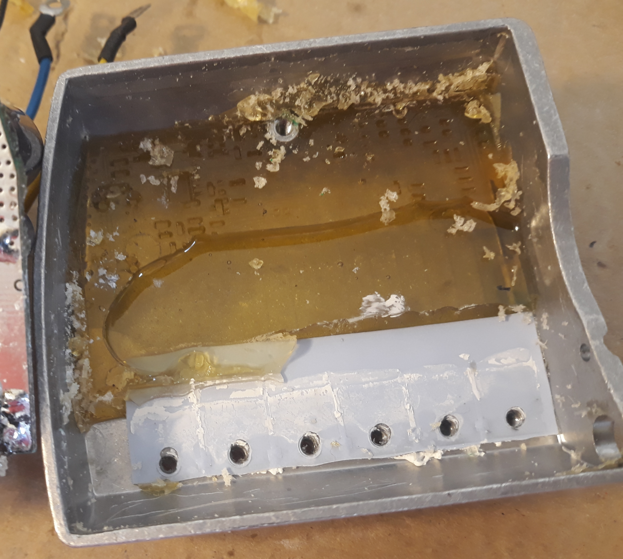
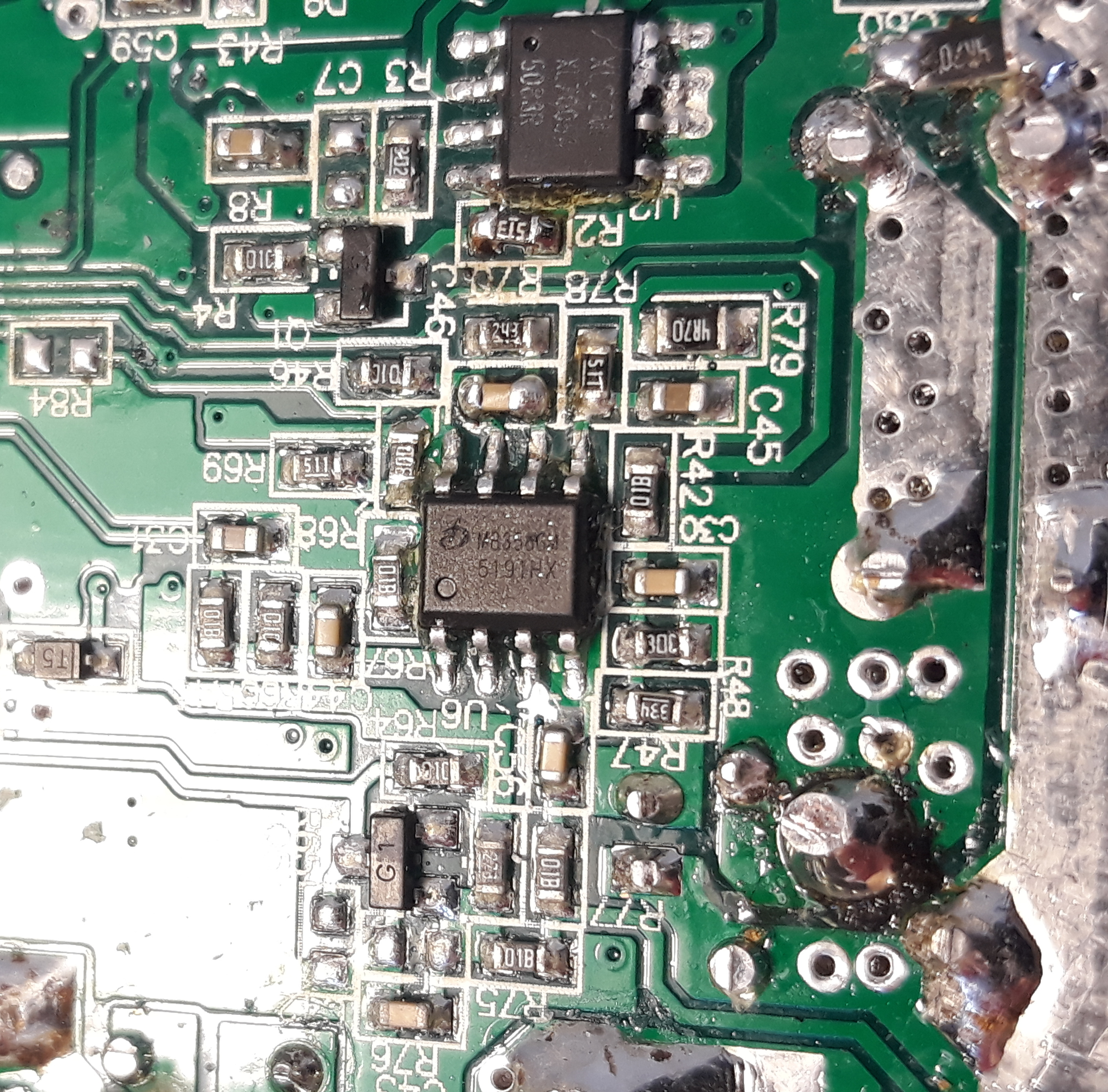
Motor controller
Motor controller with the “epoxy” removed from the microcontroller.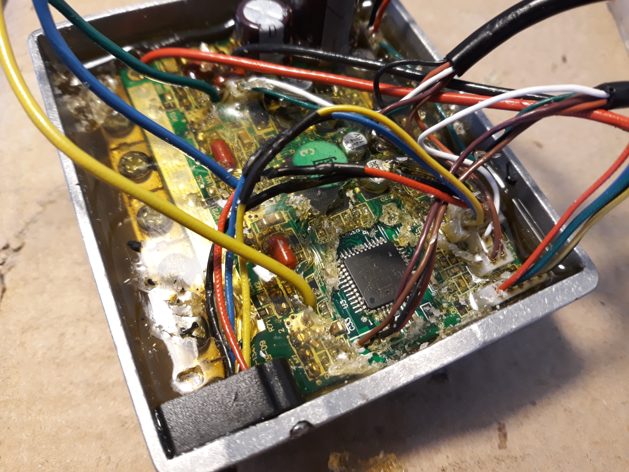
Although you can find online versions of the controller for 36V, 48V or 52V, the controller is just the same but with different configurations on the firmware.
Voltage
• Controller can run the motor from 20V battery input up to at least 60V (this values were tested)
◇ 20V will work for a 7S battery (min voltage per cell = 2.86V)
◇ 60V will work for a 14S battery
◇ controller capacitors on input voltage line are rated at 63V
Cables
• wheel speed sensor cable
◇ this cable carries the wires for STLinkV2, that is used to program and debug the firmware
◇ this cable carries the wires for the wheel speed sensor
◇ list of the wires and functions:
▪ orange wire | GND | used for: STLinkV2; wheel speed sensor
▪ brown wire | VCC | used for: STLinkV2 (optional); wheel speed sensor
▪ purple wire | RST | used for: STLinkV2
▪ black wire | SWIM | used for: STLinkV2
▪ white wire | wheel speed sensor | used for: wheel speed sensor. This signal is active low, meaning that when magnet is not in front of the sensor, this wire has 5V and with magnet in front, this wire has 0 volts.
▪ green wire | 6V for lights | 6V only when display back light is enabled
• LCD cable
◇ this cable carries the wires to power on/off the motor controller and the wires for UART TX and RX that communicate with the LCD
◇ the motor controller can be enabled by simple connect green wire to white wire and this way there is no need to use LCD
◇ list of the wires and functions:
▪ green | P+ | battery voltage!!
▪ black | GND | ground
▪ white | Vin | ground when LCD disabled and P+ (battery voltage) when LCD is enabled
▪ brown | UART TX motor controller |
▪ orange | UART RX motor controller |
▪ purple | brake | this signal is active low, meaning that when brakes are not active, this wire has 5V and brakes active, this wire has 0 volts.
Note: throttle works on original firmware even if you bought a version without throttle and in this case you just need to connected the throttle wires to the controller board.
Original firmware
Read more here.
Original Option Bytes:
•
| Linked file: TSDZ2_original_firmware_protected_option_bytes.bin |
Original firmware file:
•
| Linked file: TSDZ2_original_firmware.bin |
EEPROM:
•
| Linked file: TSDZ2_original_firmware_eeprom.bin |
Disassembled original firmware
The firmware was disassembled using Naken ASM, using the following command:
./naken_util -disasm -stm8 -address 0x8000 ./TSDZ2_original_firmware.bin > ./TSDZ2_original_firmware.asm
•
| Linked file: TSDZ2_original_firmware.asm |
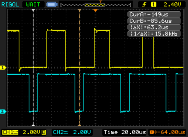
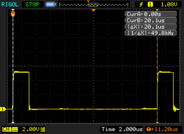
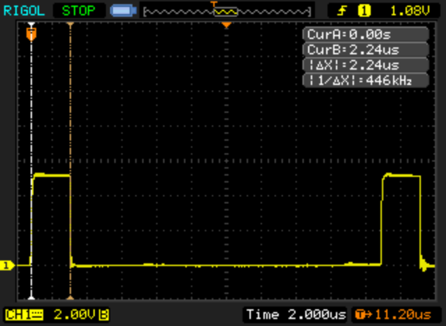
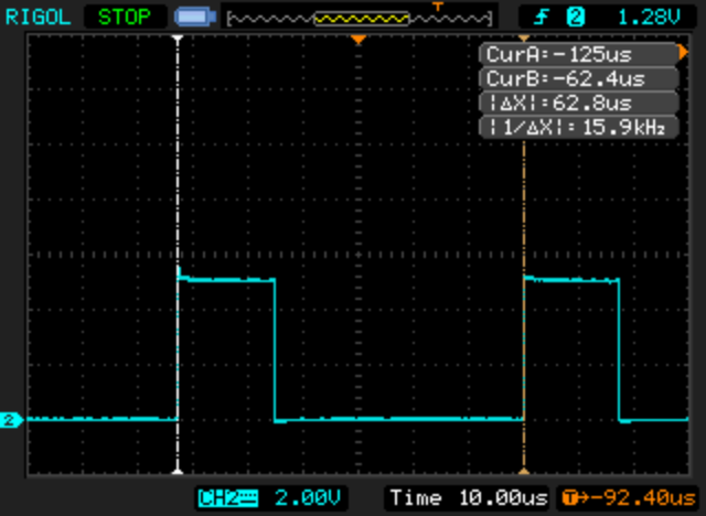
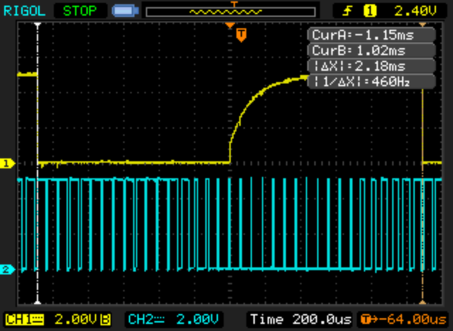
Torque sensor reading
The torque sensor signal is measured on ADC channel 3. There is a specific circuit to excite the primary coil of the torque sensor and it needs a pulse signal that is generated on PD3 and has a period of 20us and a 2us Ton:
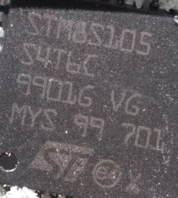
Microcontroller
Microcontroller: STM8S105S4T6C
Mosfet driver
The mosfet driver is the FAN7888 (with a clear label "EBIKE"), from OnSemi:
| Linked file: FAN7888-D.pdf |
| Linked file: FAN7888.pdf |
Mosfets
K80E08K3 Toshiba Mosfets
• mosfet N
• Max drain−source voltage: 75V
• RDS (ON) = 7.5 mΩ
| Linked file: K80E08K3-mosfets_toshiba_datasheet.pdf |
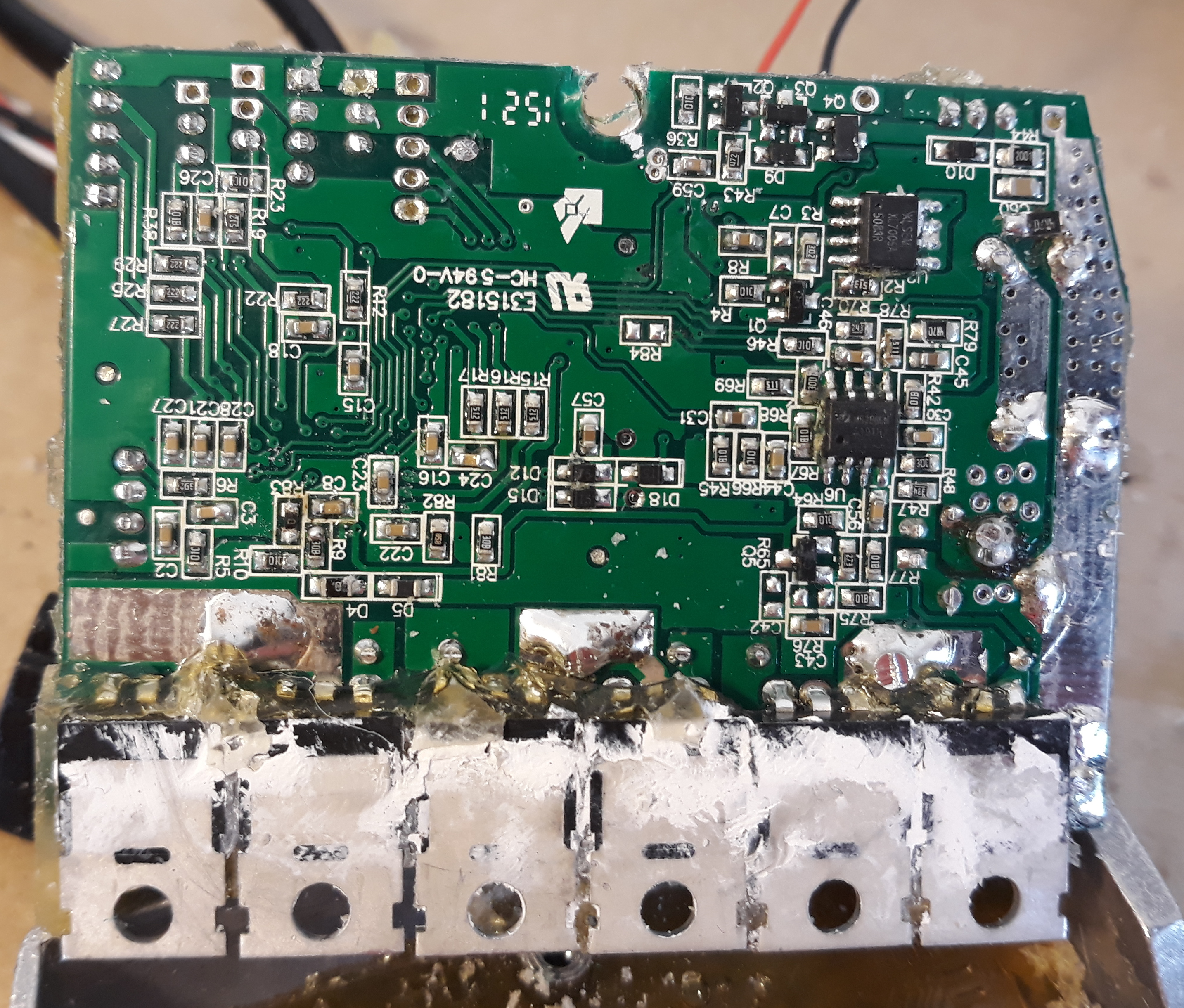
Other ICs
XL7005: seems there are 2 of this ICs being used, one on top of the PCB and other under.
• 150KHz fixed frequency PWM buck (step-down) DC/DC converter, capable of driving a 0.4A
• Wide 5V to 80V Operation Voltage
• Output Adjustable from 1.25V to 20V
• over current protection function is built inside
| Linked file: XL7005A_datasheet.pdf |
LM358: Low-Power, Dual-Operational Amplifiers.
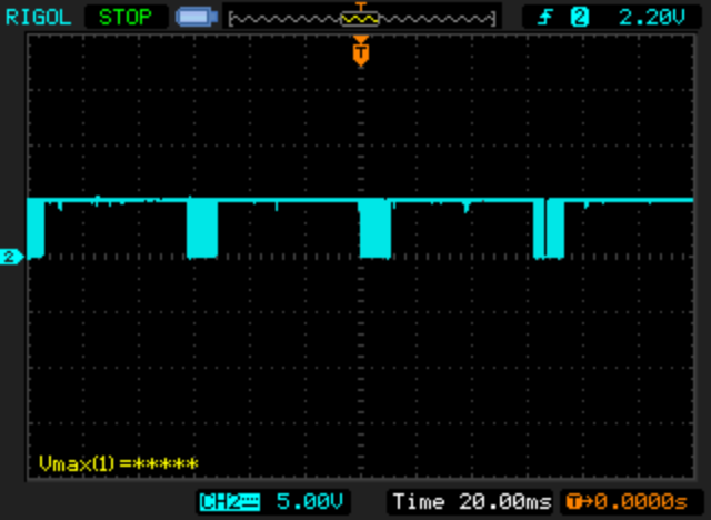
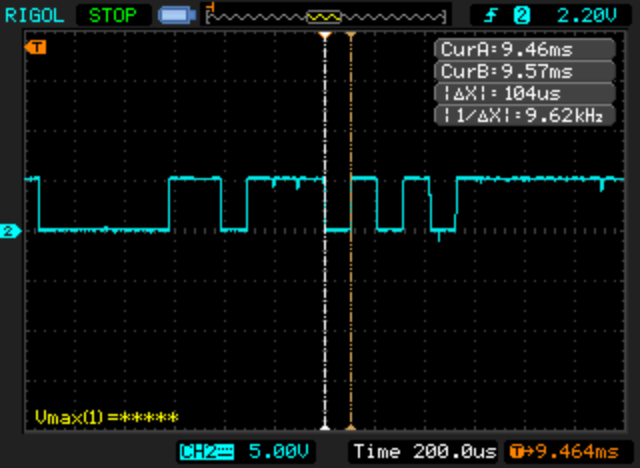
UART communication to LCD
Seems that packages are sent at about every 60ms.
The baudrate is 9600 bps.
Example of data on microcontroller UART TX pin that flows to the LCD:
Original firmware: Example of a log from data on microcontroller UART TX pin that flows to the LCD:
07 07 57 43 06 00 00 00 00 07 07 57 43 07 00 00
00 00 07 07 58 43 07 00 00 00 00 07 07 58 43 07
00 00 00 00 07 07 57 43 07 00 00 00 00 07 07 58
43 07 00 00 00 00 07 07 58 43 06 00 00 00 00 07
07 57 43 07 00 00 00 00 07 07 58 43 07 00 00 00
00 07 07 58 43 07 00 00 00 00 07 07 58 43 07 00
00 00 00 07 07 58 43 06 00 00 00 00 07 07 57 43
06 00 00 00 00 07 07 58 43 06 00 00 00 00 07 07
https://endless-sphere.com/forums/viewtopic.php?f=28&t=79788&hilit=pinout&start=175#p1238105
serial is 9600 baud, messages are for example:
LCD->motor
59 40 00 1C 00 1B D0
1. fixed/startbyte = 59?
2. byte contains flags for the selected step,light and 6kmh. 40=01000000=step1. bits from left to right as i know: unknown,step1,6kmh-active,off,step4,step3,step2,headlight
3. not sure
4. wheel size, 1C hex = 28inch
5. not sure
6. max speed, 1B hex = 27(kmh?)
7. 1byte checksum
motor->LCD
43 00 01 51 51 00 07 07 F4
1. fixed/startbyte: 0x43
2. battery level, 0=lowest (about 33V if i remember right), 0A=10 is max due to LCD (about 38V) but can be higher
3. motor state, but not sure. 01 was when off and i have seen 0D or 05 when 6kmh mode. 0x0C when motor is running.
4. not sure, seems to keep constant value of 0x59
5. pedal torque sensor value; 51=idle
6. error code, for example 08 like shown in display for low voltage
7.&8. wheel time revolution: see bellow
9. 1byte checksum as described here: https://www.lammertbies.nl/comm/info/crc-calculation.html
The 7.und 8. byte are a 16bit integer, so e.g.:
0707(hex) = 1799(dec)
6C00(hex) = 108(dec)
8901(hex) = 393(dec)
And this is basically the time that one revolution of the wheel takes in ~2,04ms steps.
So for a 28" wheel (~2,24 meters per rotation):
6C00(hex) = 108(dec) = 220,32ms = 36,5km/h
8901(hex) = 393(dec) = 801,72ms = 10,0km/h
But the LCD seems to use another value, so it is a little bit of.
I generated pulses using a AVR/Arduino to simulate speeds and to calculate the 2,04ms. I think that number comes from CPU clock + timer-prescaler or so... correct me if I'm wrong.
It looks like the possible values are from 0 to 1799.
But in reality, the display just accepts values between 30(~131,4km/h) and 1750(~2,2km/h).
Values >1750 or <30 just shown 0,0km/h. And the highest speed value the display shows is 99,9km/h anyway...
(I did send custom messages to the LCD to test this.)
i haven’t installed the motor yet, so my test possibilities are limited.
but i'm thinking about building a data logger.
and i think it is interesting that the magnet count setting at the XH18LCD is not transferred to the motor which decides to reduce its speed alone. so more than one magnet might restrict the max speed.
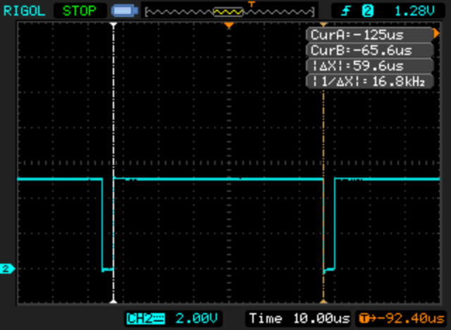
PWM signals for motor control
PWM frequency of about 16kHz:
Max duty-cycle value:
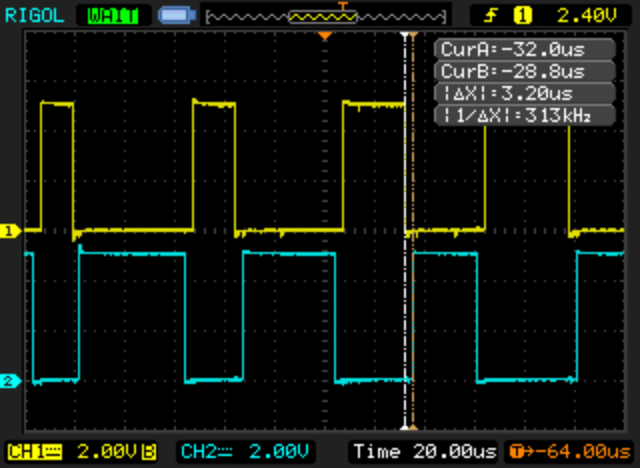
Dead time of 3.2us, example of PWM channel 1 and PWM inverted channel 1:
Sinewave or SVM PWM scheme:
Example of PWM channel 1 and PWM channel 2, center align PWM: