Motor
R and L values
Measured values for 48V motor
• L = 270uH
• R = 0.25ohm
This is between 2 windings. Assuming very little or no mutual inductance, which makes the individual phase values half those values.
• L = 135uH = 0.000135H
• R = 0.125ohm
Calculated values for 36V motor
Let's make some assumptions and deductions:
1. Lower voltage electromagnetic components have fewer turns per winding. The number of turns is directly proportional to applied voltage. So, the ratio of turns between 36V and 48V is 36/48 = 3/4.
2. Inductance is proportional to the square of number of turns, so the ratio of inductance is therefore 3*3/4/4=9/16.
3. Assume the 36V motor follows these rules. therefore, its inductance is:
L = 135uH * 9/16 = 76uH
4. Resistance is directly proportional to number of turns, so the 36V motor resistance is:
R = 0.125 * 3/4 = 0.094ohm
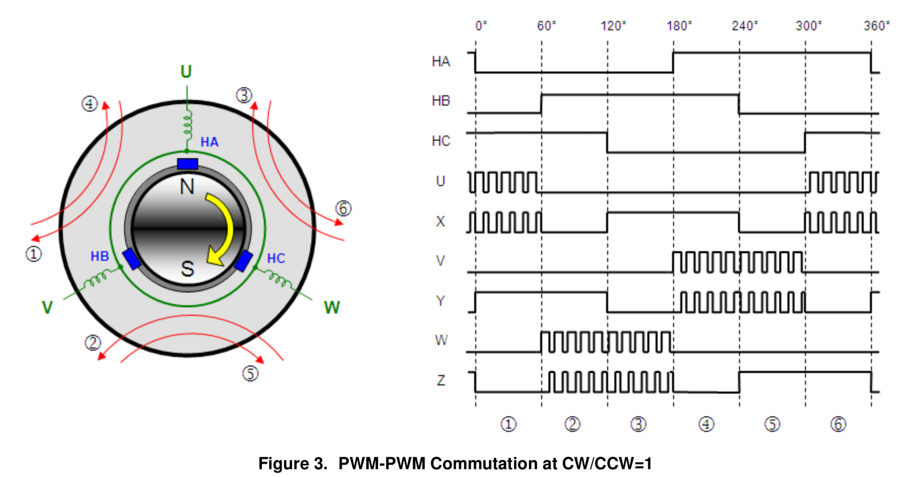
Measured BEMF and hall sensor signals
Experiments done with the 36V motor, 8 pole pairs, 4000 RPMs.
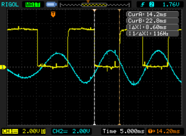
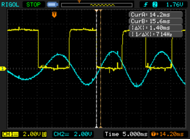
At 36V battery voltage, the measured time on hall sensors for 1 ERP was 1.94ms.
Motor has 8 poles, so the measured speed in RPMs = 60 / (0.00194 * 8) = 3866 RPMs.
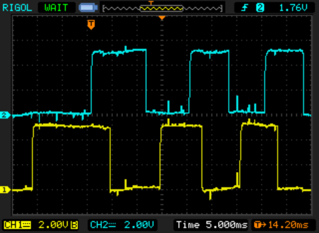
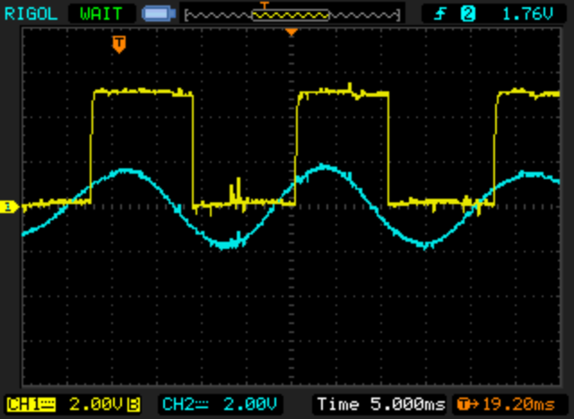
Considering motor phase labels according to BEMF measured values and this reference of hall sensors signals and rotor position:
Yellow: hall sensor A (yellow wire)
Blue: BEMF phase C (yellow wire)
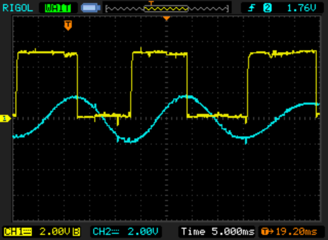
Yellow: hall sensor A (yellow wire)
Blue: BEMF phase B (green wire)
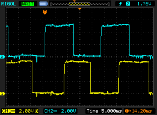
Yellow: hall sensor A (yellow wire)
Blue: BEMF phase A (blue wire)
Yellow: hall sensor A (yellow wire)
Blue: hall sensor B (green wire)
Yellow: hall sensor A (yellow wire)
Blue: hall sensor C (blue wire)