Index
Open controller and solder programming header
To solder the programming header, you will need to open the controller, remove the PCB from the metal case and solder the programming header.
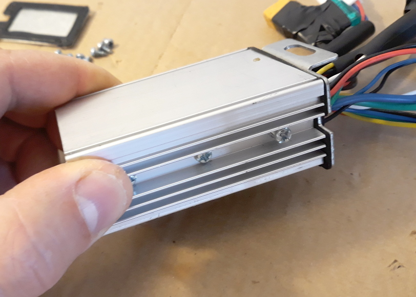
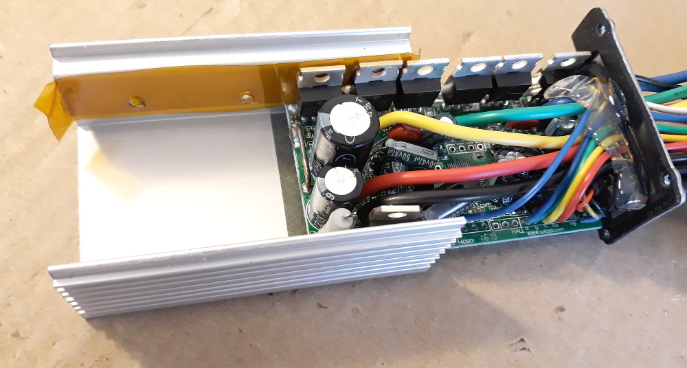
Start by removing the bolts on the lateral caps and then you can remove the top cover:
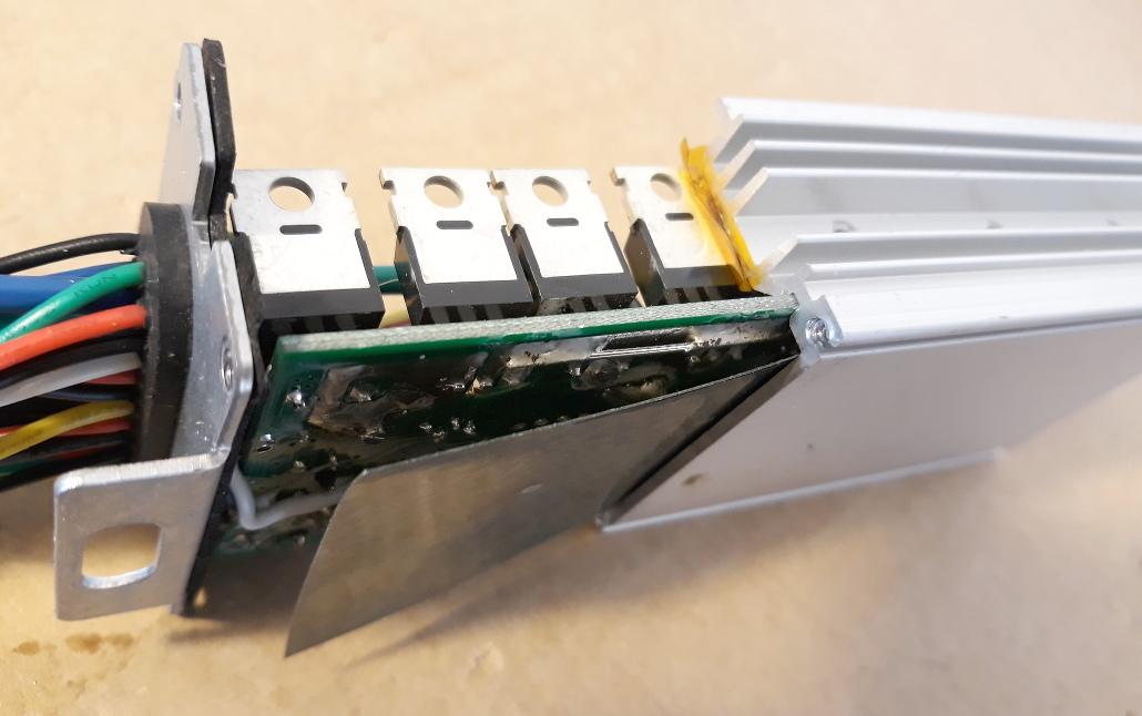
Next you will need to remove the lateral bolts, that fix the mosfets to the metal case. Remove them with the controller turned up side down, this way the metal parts inside will fall to the ground (yes, once I let the metal parts touch the PCB and burned a small mosfet because the PCB capacitors were charged).
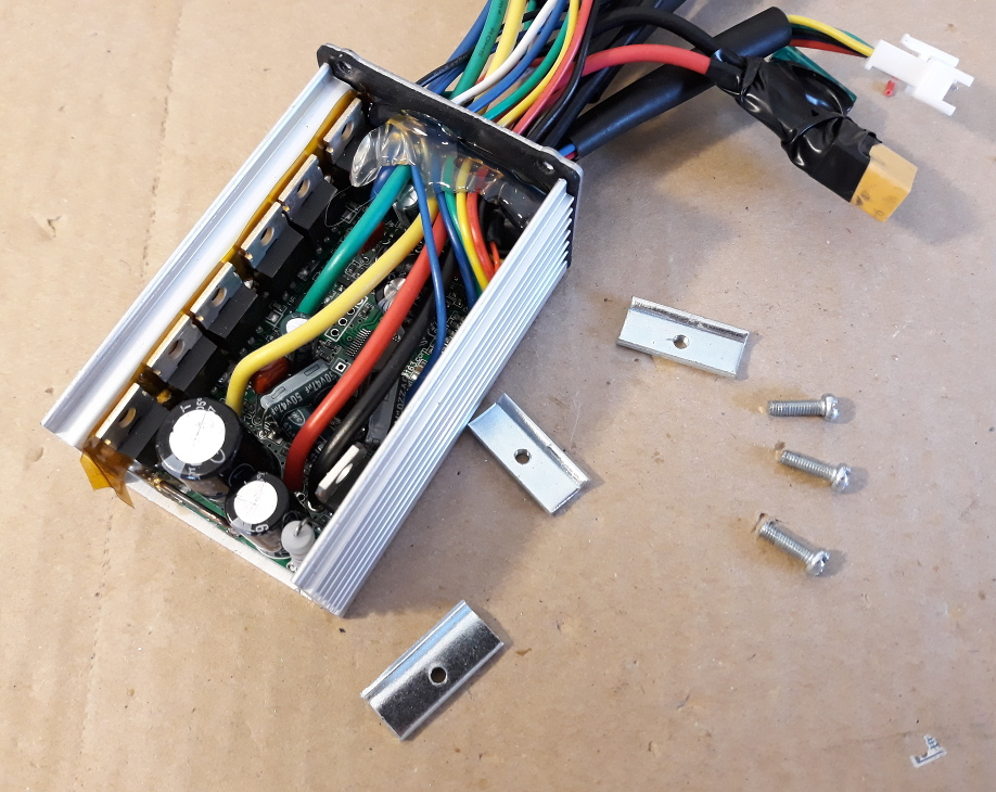
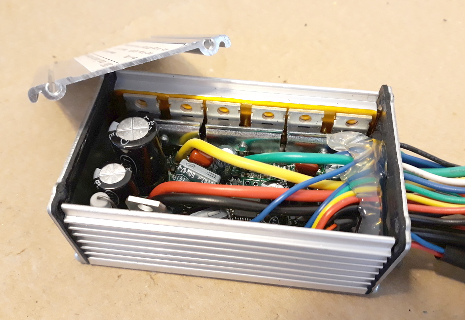
Now slide the PCB from the metal case. Note the yellow tape, that is needed to insulate the back of mosfets from the metal case - keep the yellow tape on the same place and intact:
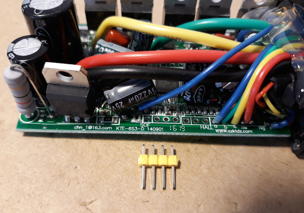
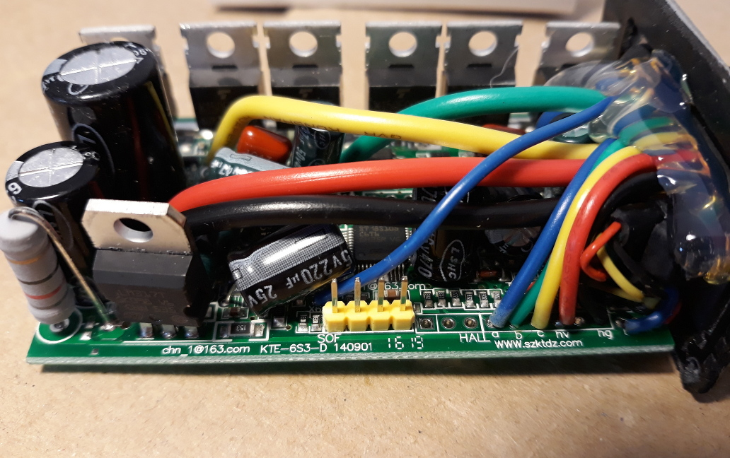
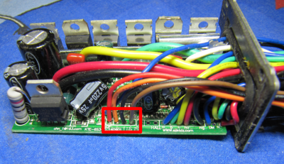
Solder a 4 pins header to the header labeled on PCB as “SOF” -- you should solder on the back of the PCB.
Pins on the header from left to right: VCC; SWIM; GND; NRST.
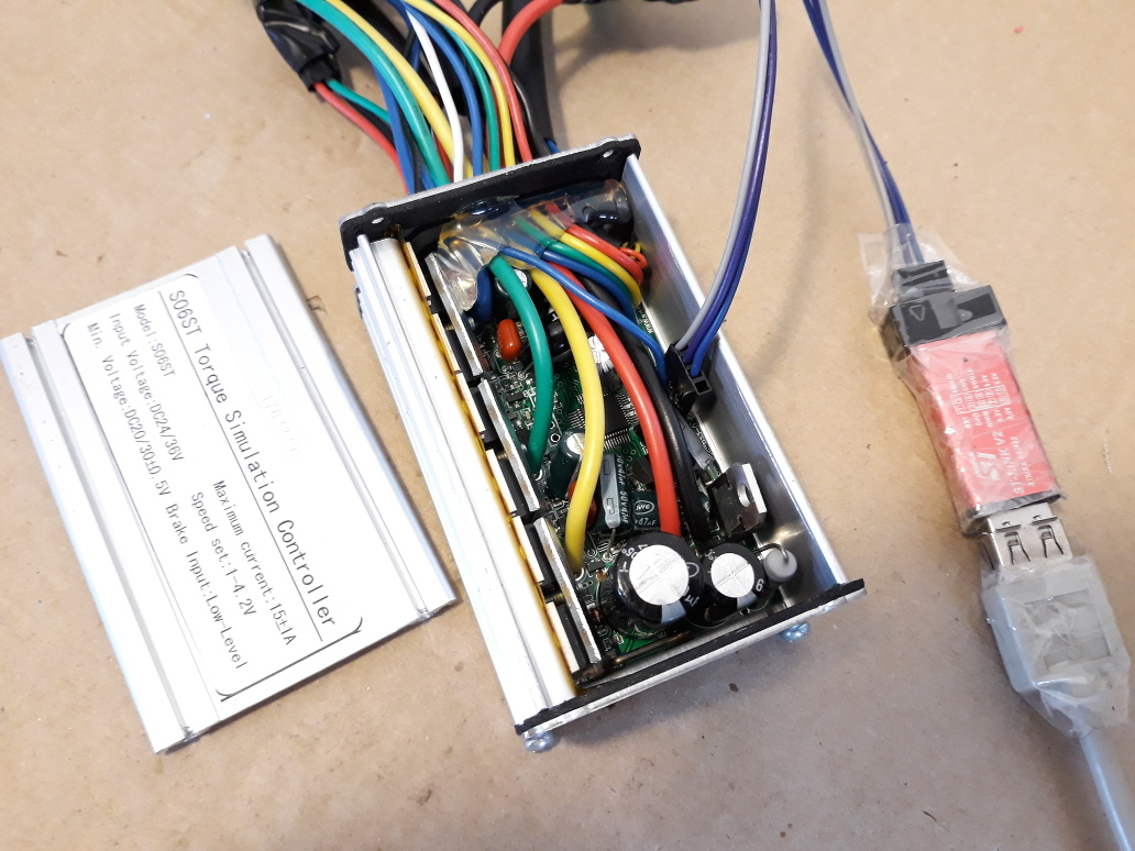
Note: of that 4 wires, optionally, you don't need to connect the VCC wire to the STLinkV2, as seen on the picture. In this case, you will need to power the controller with a battery/lab power supply.
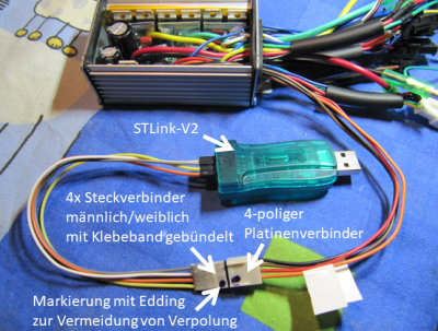
As another alternative, you can wire the programming with wires to be placed outside of the controller, as developer Stancecoke does:
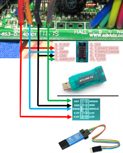
Finally it is ready to connect the STLinkV2: